Rudolph Technologies — Investor Presentation (February 2015)
14 slides from Rudolph Technologies's investor presentation, Feb 4, 2015
Slide 1: Lithography Business Group
LITHOGRAPHY BUSINESS GROUP Richard Rogoff
Slide 2: Lithography Systems Group
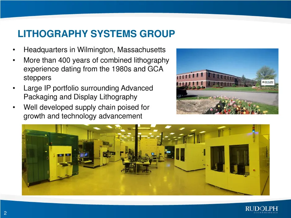
LITHOGRAPHY SYSTEMS GROUP • Headquarters in Wilmington, Massachusetts • More than 400 years of combined lithography experience dating from the 1980s and GCA steppers • Large IP portfolio surrounding Advanced Packaging and Display Lithography • Well developed supply chain poised for growth and techno
Slide 3: JetStep System: The Complete Advanced Packaging System
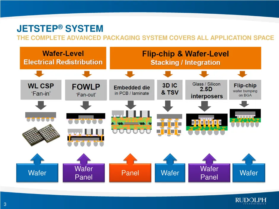
JETSTEP® SYSTEM THE COMPLETE ADVANCED PACKAGING SYSTEM COVERS ALL APPLICATION SPACE 3 Wafer Wafer Panel Panel Wafer Wafer Panel Wafer
Slide 4: Market Penetration Timeline and Status
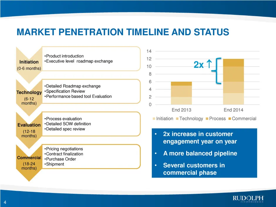
MARKET PENETRATION TIMELINE AND STATUS Initiation (0-6 months) •Product introduction •Executive level roadmap exchange Technology (6-12 months) •Detailed Roadmap exchange •Specification Review •Performance based tool Evaluation Evaluation (12-18 months) •Process evaluation •Detailed SOW definition •
Slide 5: Market Predictions
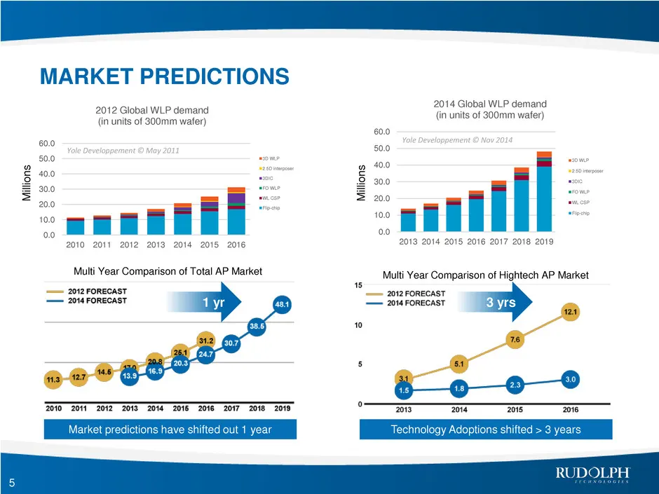
MARKET PREDICTIONS 0.0 10.0 20.0 30.0 40.0 50.0 60.0 2010 2011 2012 2013 2014 2015 2016 2012 Global WLP demand (in units of 300mm wafer) 3D WLP 2.5D interposer 3DIC FO WLP WL CSP Flip-chip Yole Developpement © May 2011 5 0.0 10.0 20.0 30.0 40.0 50.0 60.0 2013 2014 2015 2016 2017 2018 2019 2014 Globa
Slide 6: Advanced Packaging Lithography Challenges
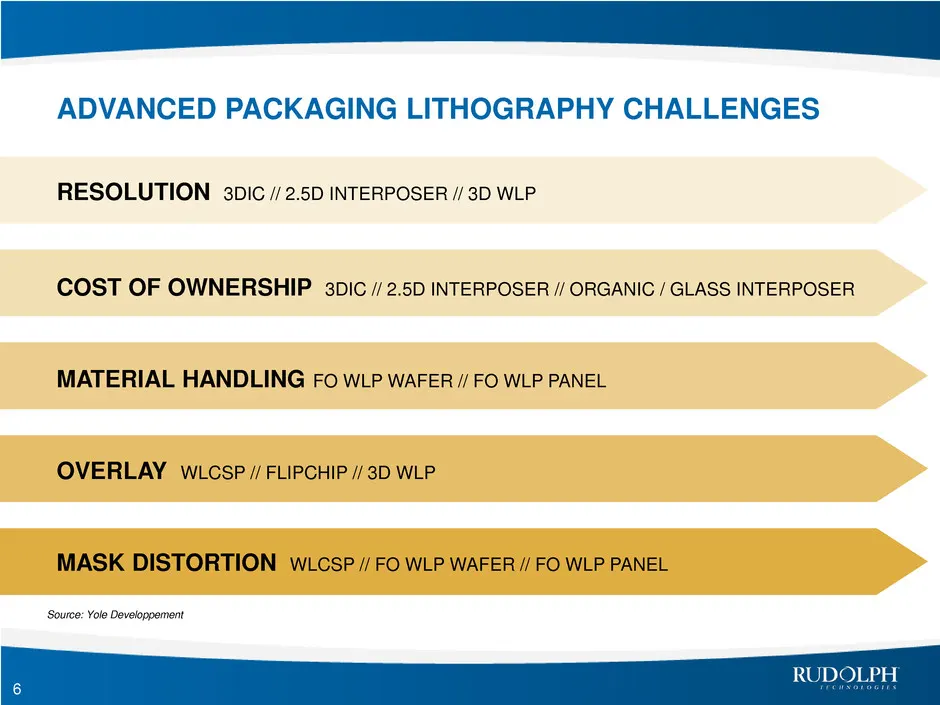
ADVANCED PACKAGING LITHOGRAPHY CHALLENGES 6 Source: Yole Developpement RESOLUTION 3DIC // 2.5D INTERPOSER // 3D WLP COST OF OWNERSHIP 3DIC // 2.5D INTERPOSER // ORGANIC / GLASS INTERPOSER MATERIAL HANDLING FO WLP WAFER // FO WLP PANEL OVERLAY WLCSP // FLIPCHIP // 3D WLP MASK DISTORTION WLCSP // FO W
Slide 7: RDL Development Program
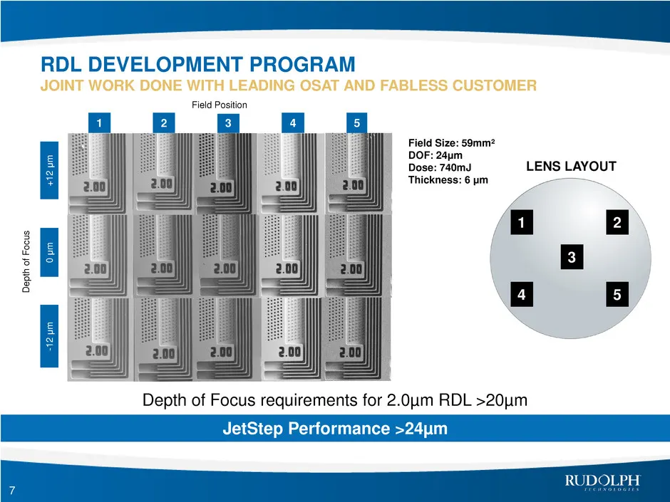
-1 2 μ m 0 μ m + 1 2 μ m 5 2 3 4 1 Dep th o f F o c u s Field Position Field Size: 59mm² DOF: 24μm Dose: 740mJ Thickness: 6 μm 1 3 4 5 2 LENS LAYOUT Depth of Focus requirements for 2.0µm RDL >20µm JetStep Performance >24µm RDL DEVELOPMENT PROGRAM JOINT WORK DONE WITH LEADING OSAT AND FABLESS CUSTOME
Slide 8: Electroplated Copper Pillar Development
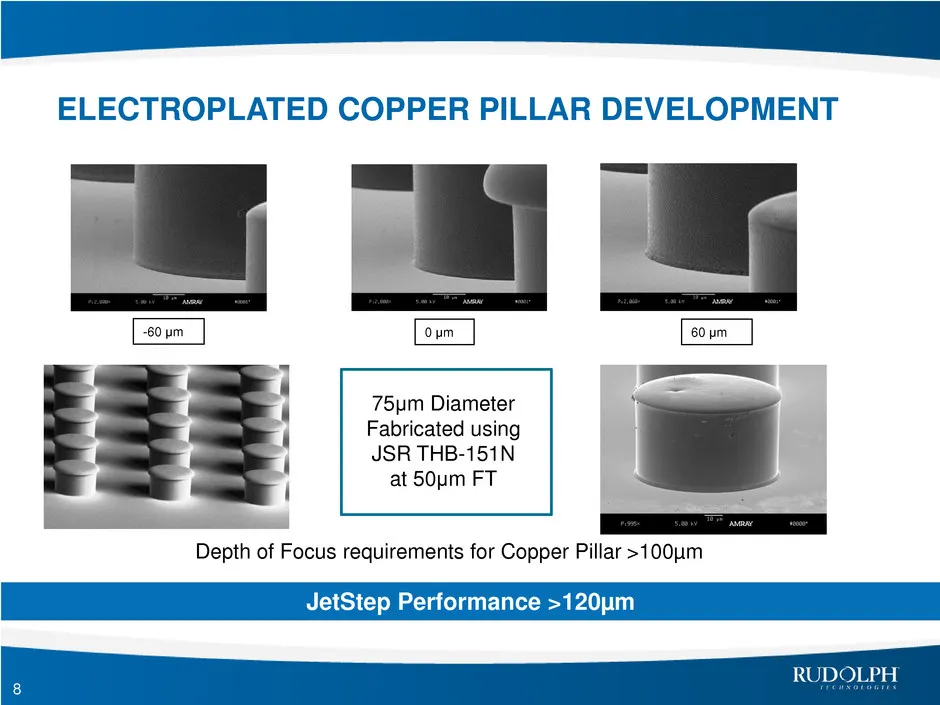
75μm Diameter Fabricated using JSR THB-151N at 50μm FT Depth of Focus requirements for Copper Pillar >100µm -60 μm 60 μm 0 μm ELECTROPLATED COPPER PILLAR DEVELOPMENT 8 JetStep Performance >120µm
Slide 9: Customer Proven Value of Ownership
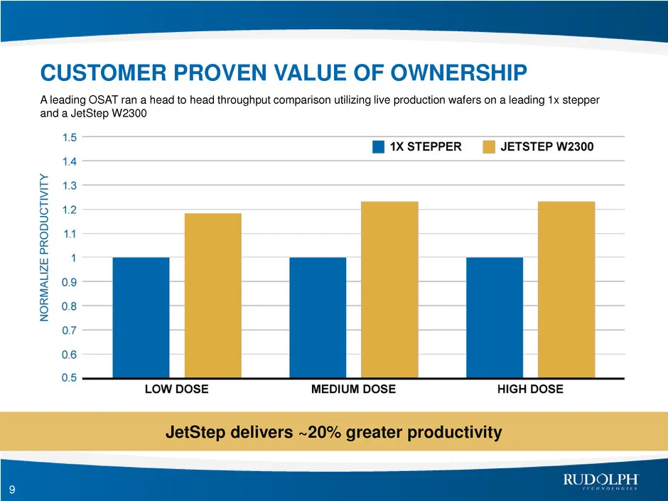
9 A leading OSAT ran a head to head throughput comparison utilizing live production wafers on a leading 1x stepper and a JetStep W2300 CUSTOMER PROVEN VALUE OF OWNERSHIP JetStep delivers ~20% greater productivity
Slide 10: JetStep's Industry Leading Material Handler
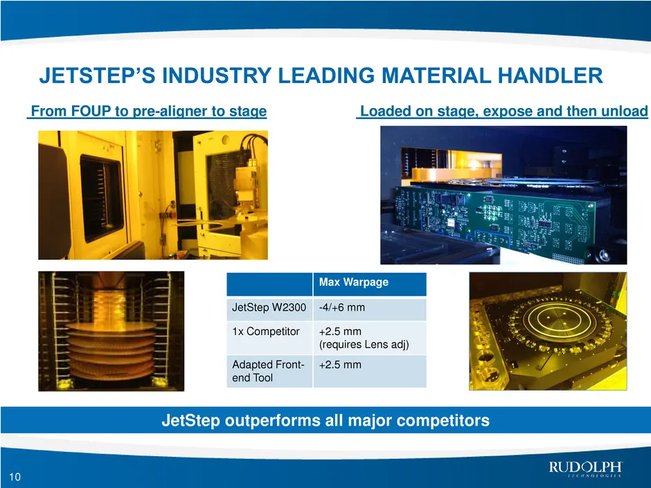
From FOUP to pre-aligner to stage 10 Loaded on stage, expose and then unload Max Warpage JetStep W2300 -4/+6 mm 1x Competitor +2.5 mm (requires Lens adj) Adapted Front- end Tool +2.5 mm JETSTEP’S INDUSTRY LEADING MATERIAL HANDLER JetStep outperforms all major competitors
Slide 11: Customer Product Overlay Evaluation for eWLB
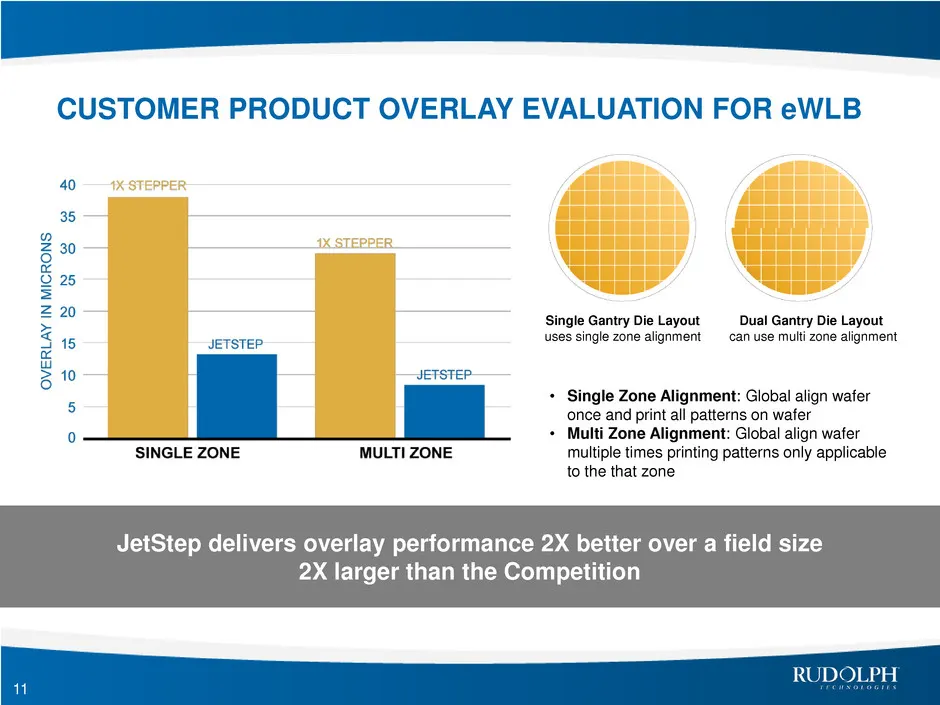
11 • Single Zone Alignment: Global align wafer once and print all patterns on wafer • Multi Zone Alignment: Global align wafer multiple times printing patterns only applicable to the that zone Single Gantry Die Layout uses single zone alignment Dual Gantry Die Layout can use multi zone alignment 1 x
Slide 12: The 2X Reduction Single Sided Telecentric Lens
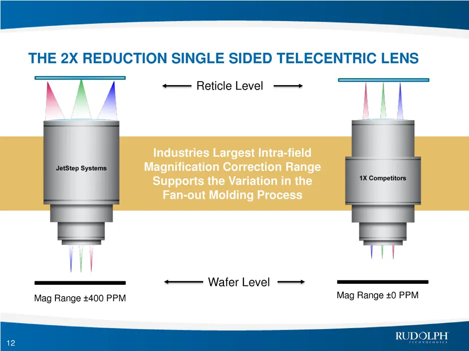
12 THE 2X REDUCTION SINGLE SIDED TELECENTRIC LENS Industries Largest Intra-field Magnification Correction Range Supports the Variation in the Fan-out Molding Process Wafer Level Reticle Level Mag Range ±400 PPM Mag Range ±0 PPM
Slide 13: Summary
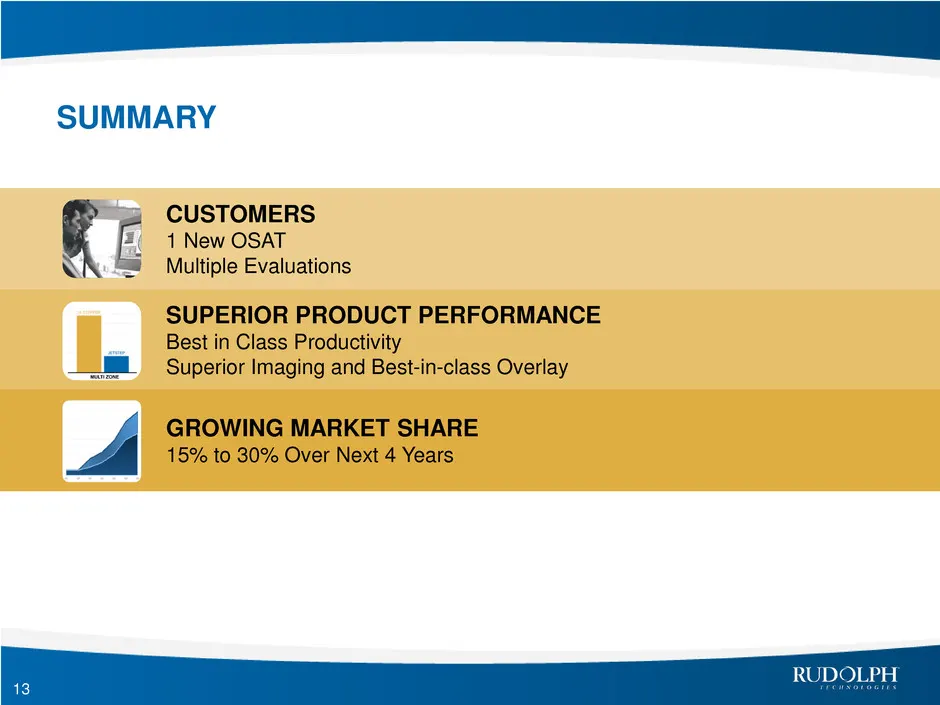
13 SUMMARY CUSTOMERS 1 New OSAT Multiple Evaluations SUPERIOR PRODUCT PERFORMANCE Best in Class Productivity Superior Imaging and Best-in-class Overlay GROWING MARKET SHARE 15% to 30% Over Next 4 Years
Slide 14: February 4, 2015
February 4, 2015
Source: SEC EDGAR · 8-K filed Feb 4, 2015
More decks from Rudolph Technologies Inc
 Merger or Acquisition (June 2019)12 slides · Jun 24, 2019
 Merger or Acquisition (June 2019)18 slides · Jun 24, 2019
 Investor Day (September 2017)79 slides · Sep 14, 2017
 Shareholder Meeting (May 2015)32 slides · May 22, 2015
 Investor Presentation (February 2015)13 slides · Feb 4, 2015
 Investor Day (February 2015)13 slides · Feb 4, 2015