Data Modul AG · XETR:DAM
Data Modul — Technical Presentation (April 2011)
19 slides from Data Modul's technical presentation, Apr 28, 2011
Slide 1: 1
1
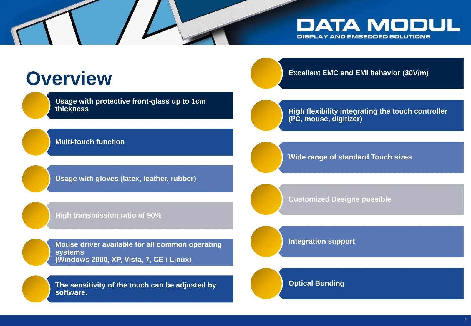
Slide 2: Overview
Excellent EMC and EMI behavior (30V/m) Overview Usage with protective front-glass up to 1cm thickness High flexibility integrating the touch controller (I²C, mouse, digitizer) Multi-touch function Wide range of standard Touch sizes Usage with gloves (latex, leather, rubber) Customized Designs possib
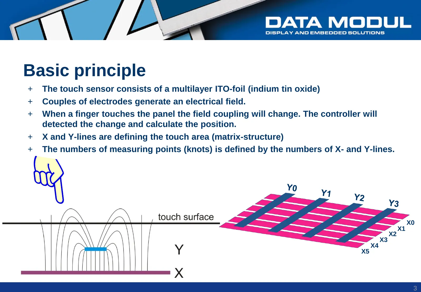
Slide 3: Basic principle
Basic principle + The touch sensor consists of a multilayer ITO-foil (indium tin oxide) + Couples of electrodes generate an electrical field. + When a finger touches the panel the field coupling will change. The controller will detected the change and calculate the position. + X and Y-lines are defi
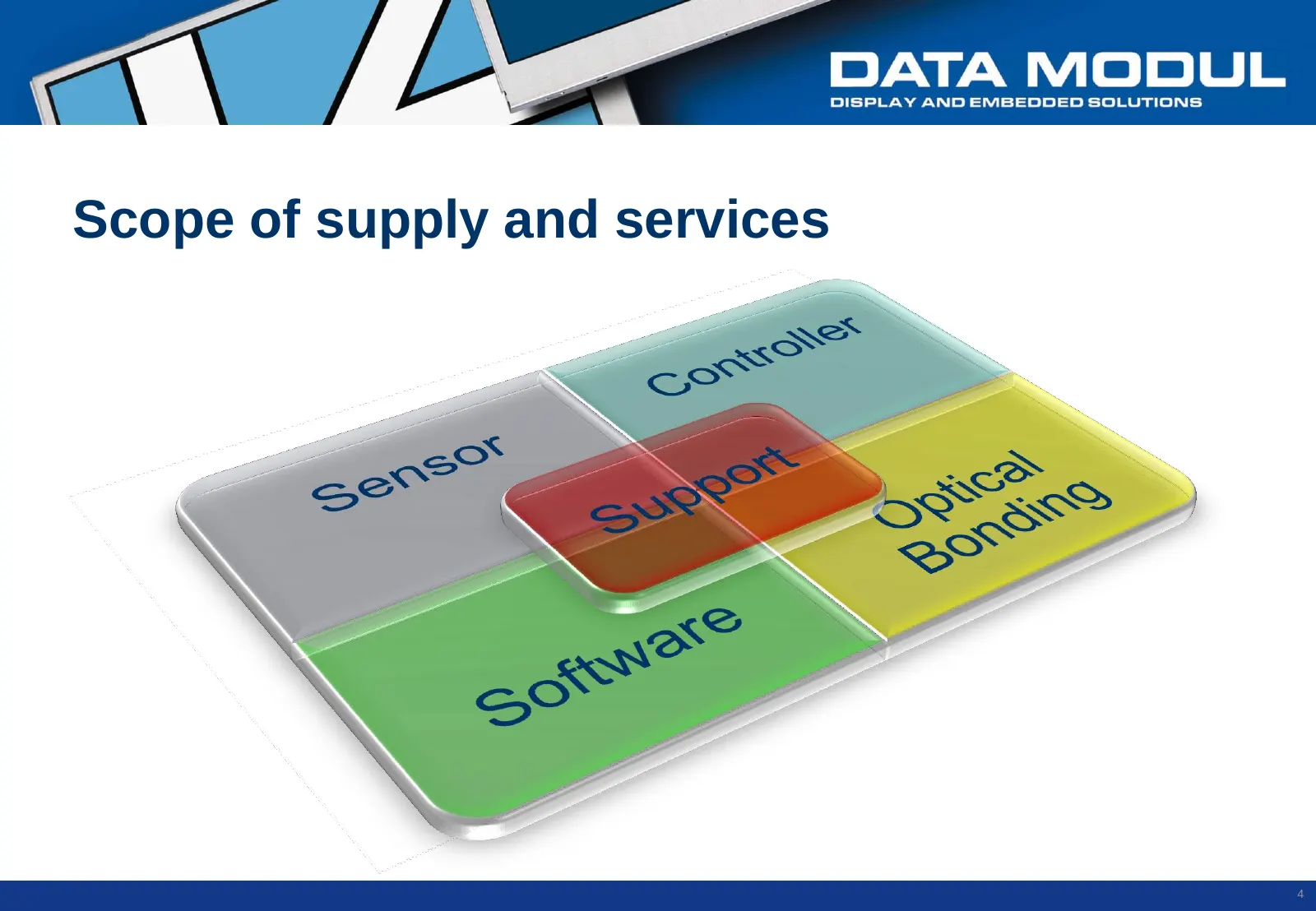
Slide 4: Scope of supply and services
Scope of supply and services 4
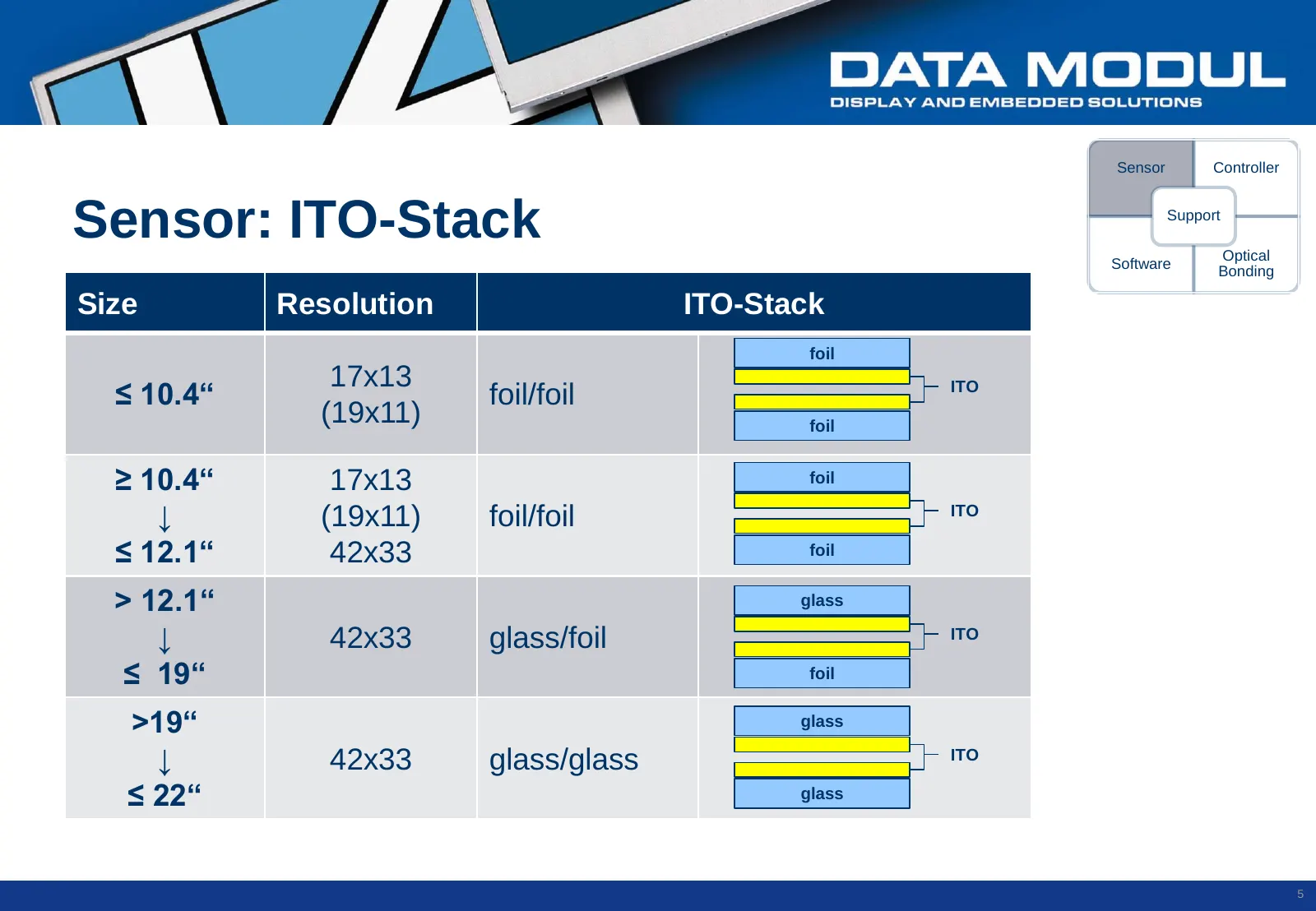
Slide 5: Sensor: ITO-Stack
Sensor Controller Sensor: ITO-Stack Support Optical Software Bonding Size Resolution ITO-Stack foil 17x13 ≤ 10.4“ foil/foil ITO (19x11) foil ≥ 10.4“ 17x13 foil ↓ (19x11) foil/foil ITO ≤ 12.1“ 42x33 foil > 12.1“ glass ↓ 42x33 glass/foil ITO ≤ 19“ foil >19“ glass ↓ 42x33 glass/glass ITO ≤ 22“ glass 5
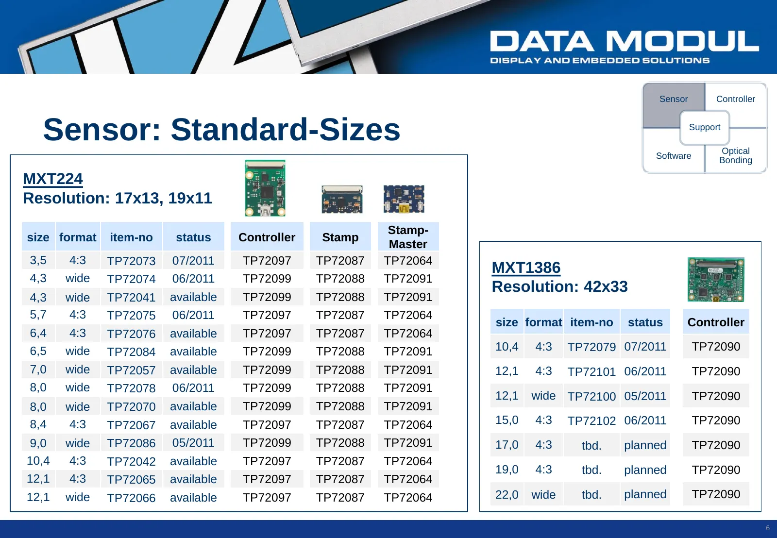
Slide 6: Sensor: Standard-Sizes
Sensor Controller Sensor: Standard-Sizes Support Optical Software Bonding MXT224 Resolution: 17x13, 19x11 Stamp- size format item-no status Controller Stamp Master 3,5 4:3 TP72073 07/2011 TP72097 TP72087 TP72064 MXT1386 4,3 wide TP72074 06/2011 TP72099 TP72088 TP72091 Resolution: 42x33 4,3 wide TP72
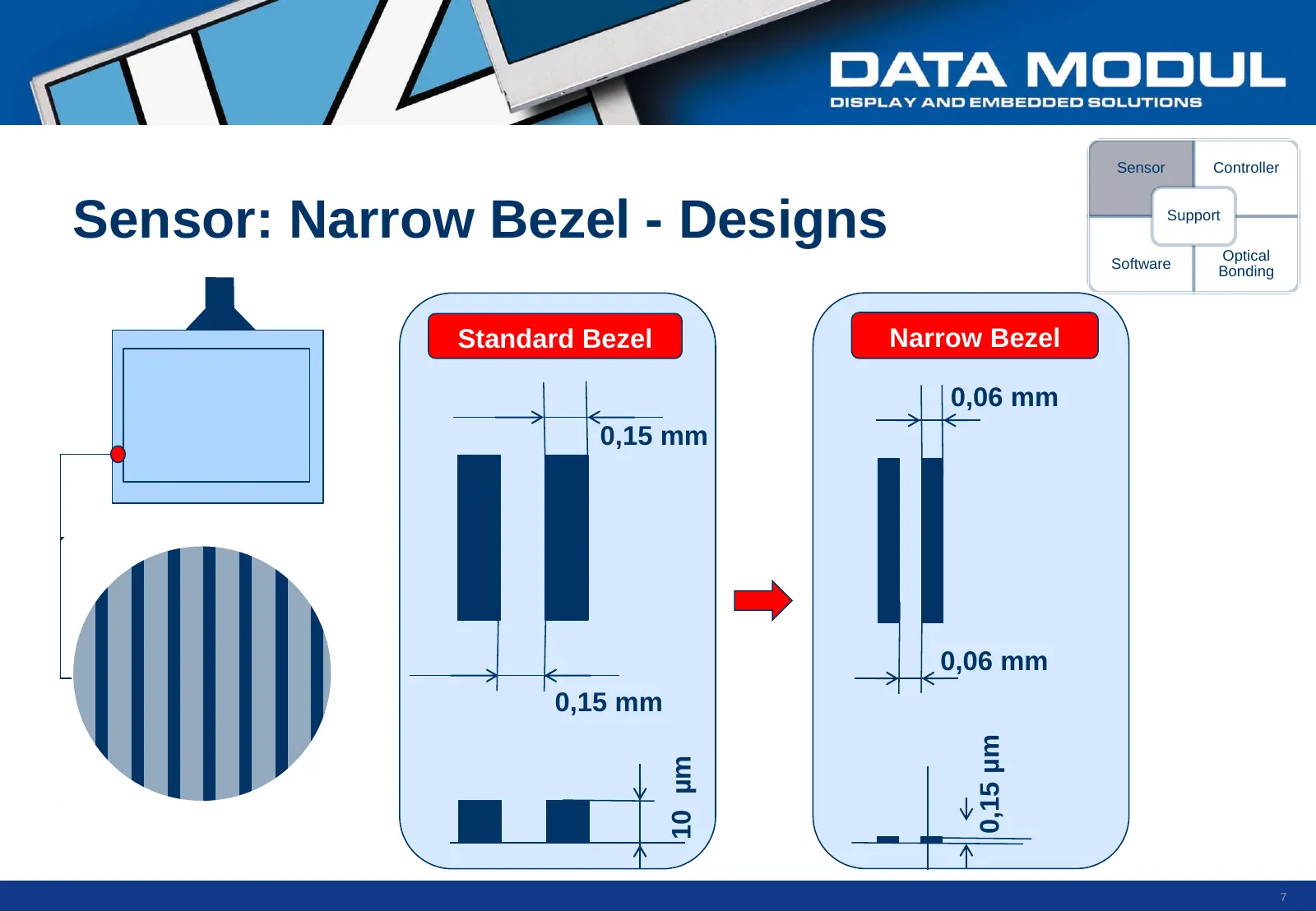
Slide 7: Sensor: Narrow Bezel - Designs
Sensor Controller Sensor: Narrow Bezel - Designs Support Optical Software Bonding Standard Bezel Narrow Bezel 0,06 mm 0,15 mm 0,06 mm 0,15 mm 0,15 µm 10 µm 7
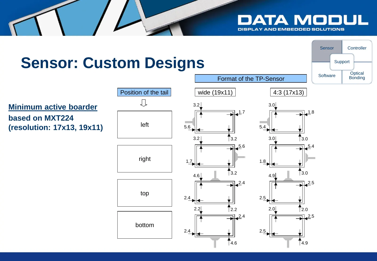
Slide 8: Sensor: Custom Designs
Sensor Controller Sensor: Custom Designs Support Optical Software Format of the TP-Sensor Bonding Position of the tail wide (19x11) 4:3 (17x13) 3.2 3.0 Minimum active boarder 1.7 1.8 based on MXT224 left (resolution: 17x13, 19x11) 5.6 5.4 3.2 3.2 3.0 3.0 5.6 5.4 right 1.7 1.8 3.2 3.0 4.6 4.9 2.4 2.5
Slide 9: Controller: Overview
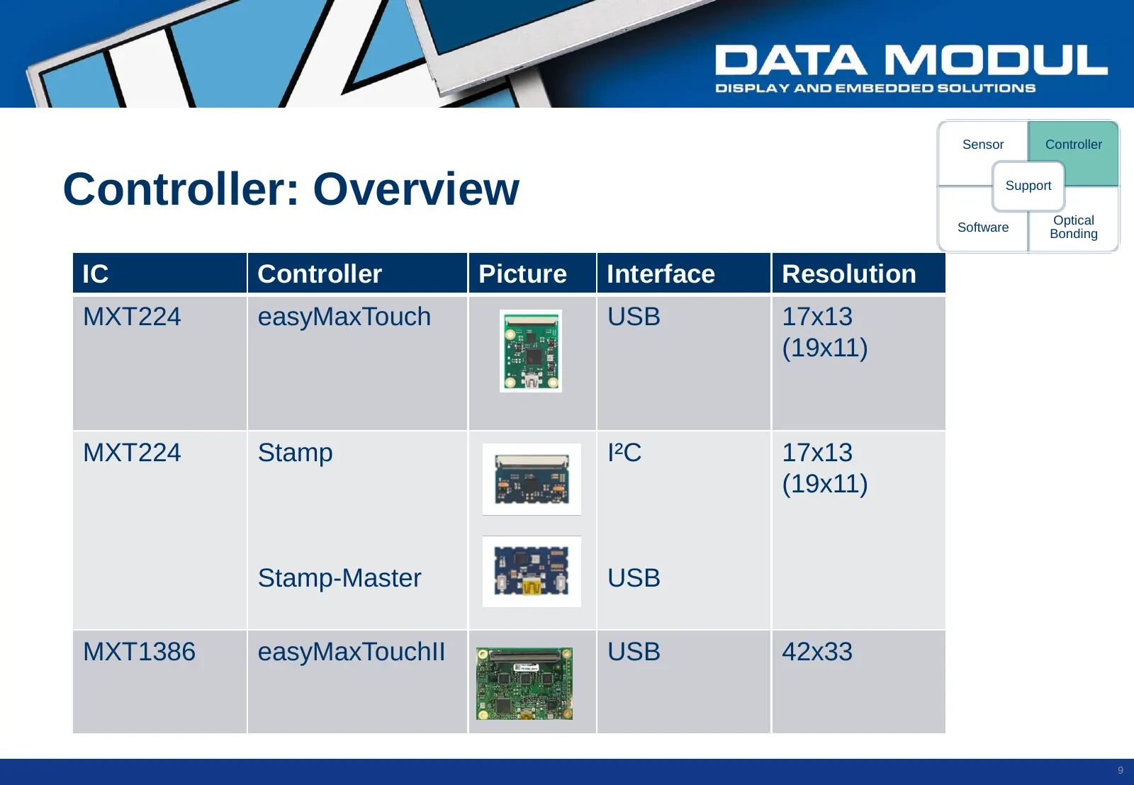
Sensor Controller Controller: Overview Support Optical Software Bonding IC Controller Picture Interface Resolution MXT224 easyMaxTouch USB 17x13 (19x11) MXT224 Stamp I²C 17x13 (19x11) Stamp-Master USB MXT1386 easyMaxTouchII USB 42x33 ´ 9
Slide 10: Controller: Stamp Concept
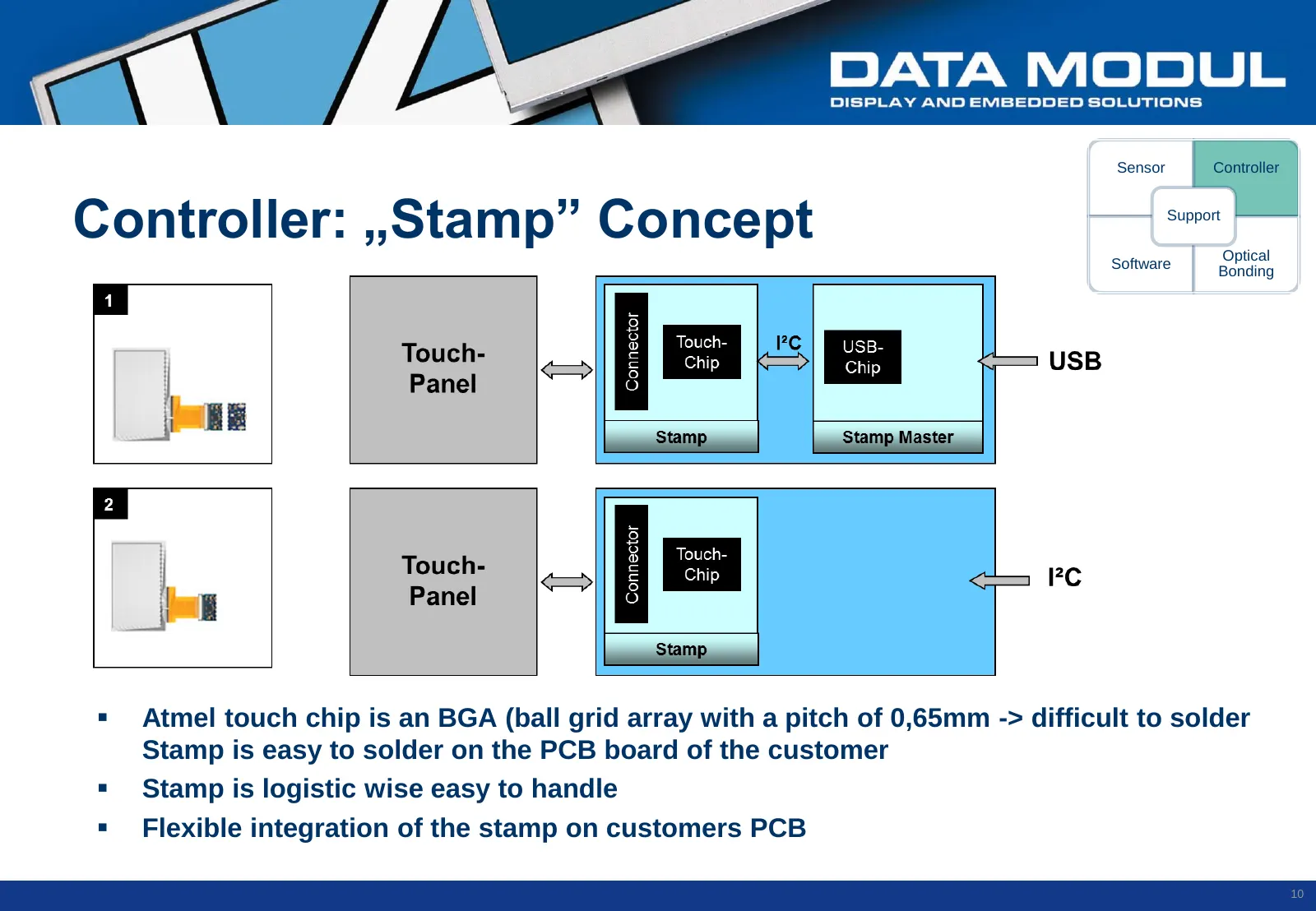
Sensor Controller Controller: „Stamp” Concept Support Optical Software Bonding Atmel touch chip is an BGA (ball grid array with a pitch of 0,65mm -> difficult to solder Stamp is easy to solder on the PCB board of the customer Stamp is logistic wise easy to handle Flexible integration of the st
Slide 11: USB-Integration: easyTouch-Controller
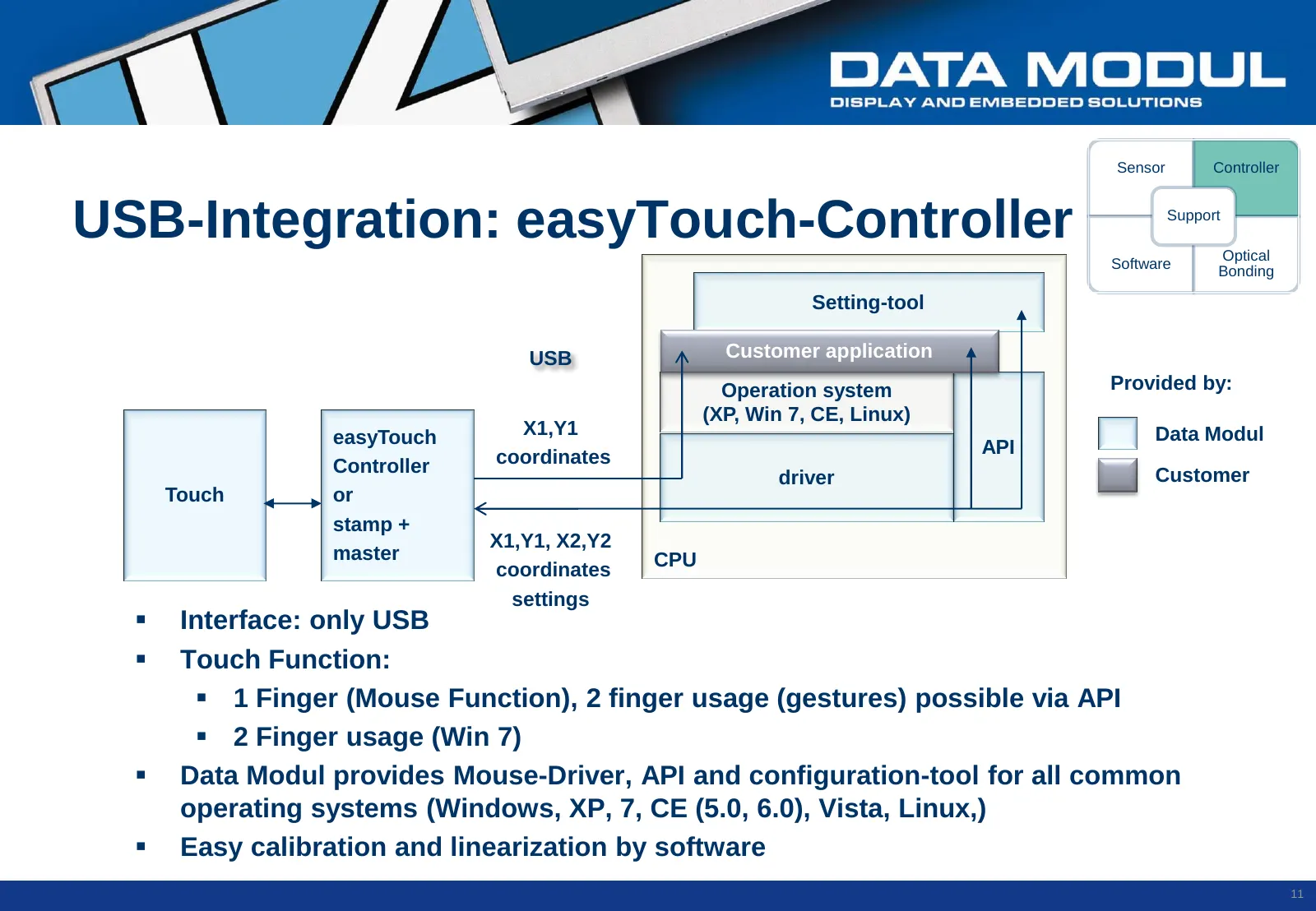
Sensor Controller USB-Integration: easyTouch-Controller Support Optical Software Bonding Setting-tool USB Customer application Operation system Provided by: (XP, Win 7, CE, Linux) easyTouch X1,Y1 Data Modul API Controller coordinates driver Customer Touch or stamp + X1,Y1, X2,Y2 master CPU coordinat
Slide 12: I²C-Integration on custom-board
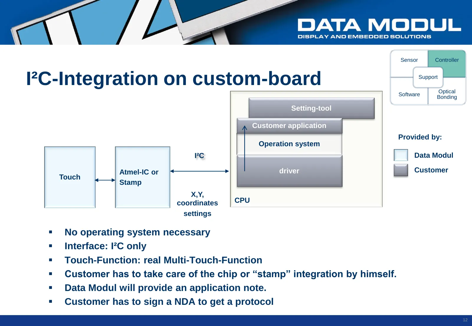
Sensor Controller I²C-Integration on custom-board Support Optical Software Bonding Setting-tool Customer application Provided by: Operation system I²C Data Modul Atmel-IC or driver Customer Touch Stamp X,Y, coordinates CPU settings No operating system necessary Interface: I²C only Touch-Functi
Slide 13: Digitizer-Integration Win 7
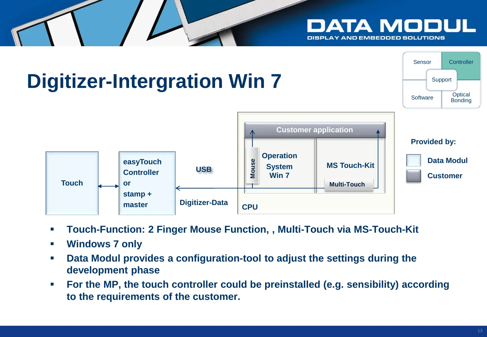
Sensor Controller Digitizer-Intergration Win 7 Support Optical Software Bonding Customer application Provided by: Operation Data Modul Mouse easyTouch MS Touch-Kit USB System Controller Win 7 Customer Touch or Multi-Touch stamp + master Digitizer-Data CPU Touch-Function: 2 Finger Mouse Function, ,
Slide 14: Software: Overview
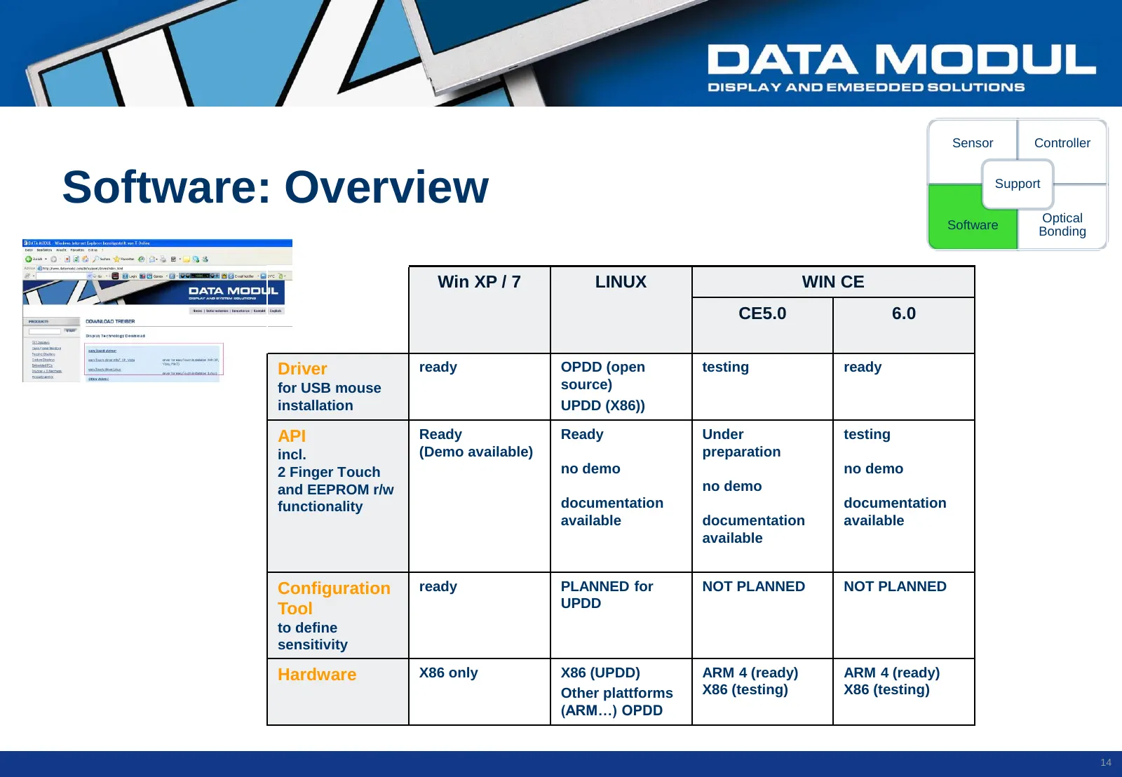
Sensor Controller Software: Overview Support Optical Software Bonding Win XP / 7 LINUX WIN CE CE5.0 6.0 Driver ready OPDD (open testing ready for USB mouse source) installation UPDD (X86)) API Ready Ready Under testing incl. (Demo available) preparation 2 Finger Touch no demo no demo and EEPROM r/w
Slide 15: Software: Driver and Setting Tool
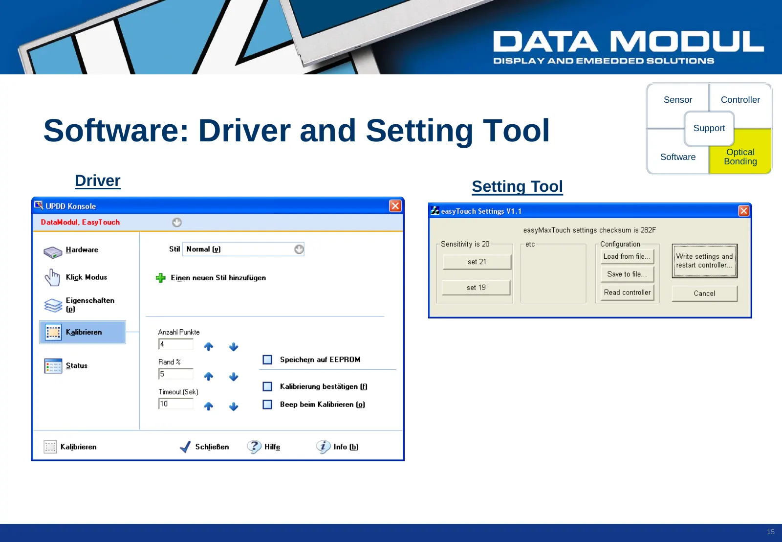
Sensor Controller Software: Driver and Setting Tool Support Optical Software Bonding Driver Setting Tool 15
Slide 16: Opt. Bonding
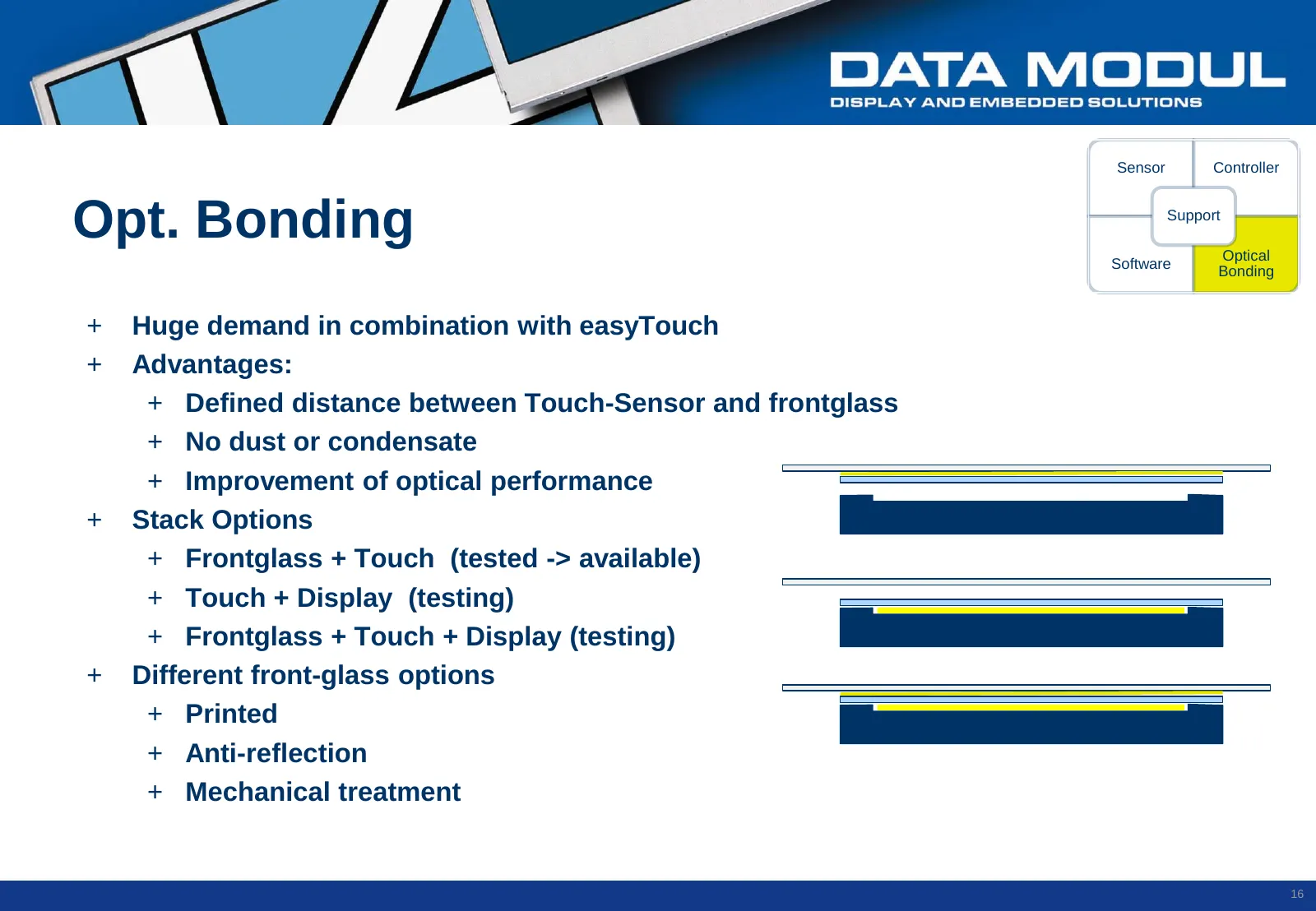
Sensor Controller Opt. Bonding Support Optical Software Bonding + Huge demand in combination with easyTouch + Advantages: + Defined distance between Touch-Sensor and frontglass + No dust or condensate + Improvement of optical performance + Stack Options + Frontglass + Touch (tested -> available) + T
Slide 17: Support: Overview
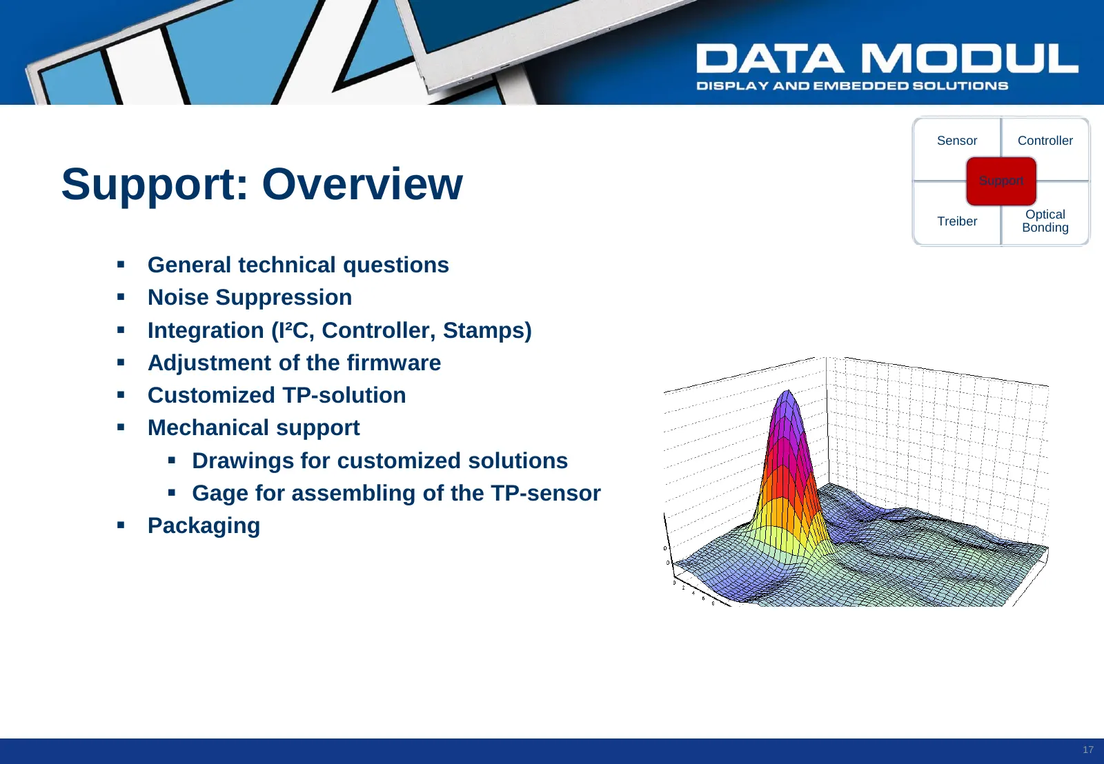
Sensor Controller Support: Overview Support Optical Treiber Bonding General technical questions Noise Suppression Integration (I²C, Controller, Stamps) Adjustment of the firmware Customized TP-solution Mechanical support Drawings for customized solutions Gage for assembling of the TP
Slide 18: Support: Noise Suppression
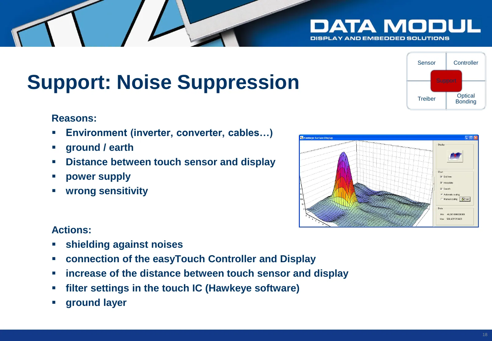
Sensor Controller Support: Noise Suppression Support Optical Treiber Bonding Reasons: Environment (inverter, converter, cables…) ground / earth Distance between touch sensor and display power supply wrong sensitivity Actions: shielding against noises connection of the easyTouch Control

Slide 19: Contact
Contact: Stefan Worlitzer Produktmarketing sworlitzer@data-modul.com Tel. +49 -89 -56017 – 223 Head Office Germany Data Modul AG Landsberger Str. 322 D- 80687 Munich Tel. +49 -89 -56017 - 0 Fax. +49 -89 -56017 - 119 info@data-modul.com www.data-modul.com 19
Source: Internet Archive copy of data-modul.com