INFICON Holding AG · SIX:IFCN
INFICON — Gulf Coast Conference 2012
29 slides from INFICON's conference presentation, Oct 17, 2012
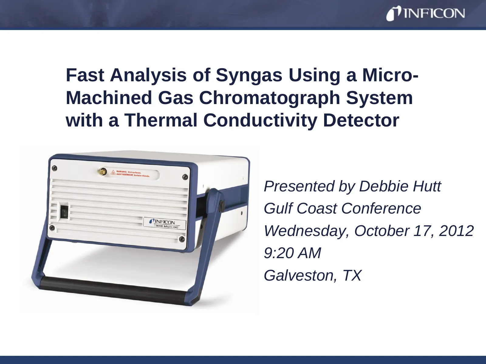
Slide 1: Fast Analysis of Syngas Using a Micro-Machined Gas Chromatograph System
Fast Analysis of Syngas Using a Micro- Machined Gas Chromatograph System with a Thermal Conductivity Detector Presented by Debbie Hutt Gulf Coast Conference Wednesday, October 17, 2012 9:20 AM Galveston, TX
Slide 2: Presentation Outline
Presentation Outline Introduction Syngas Composition Syngas Produced from Coal Gasification • Environmental Implications • Industry Example Syngas Produced from Natural Gas (Steam Methane Reforming) • Environmental Implications • Industry Example Gas Chromatography as an Analysis Option
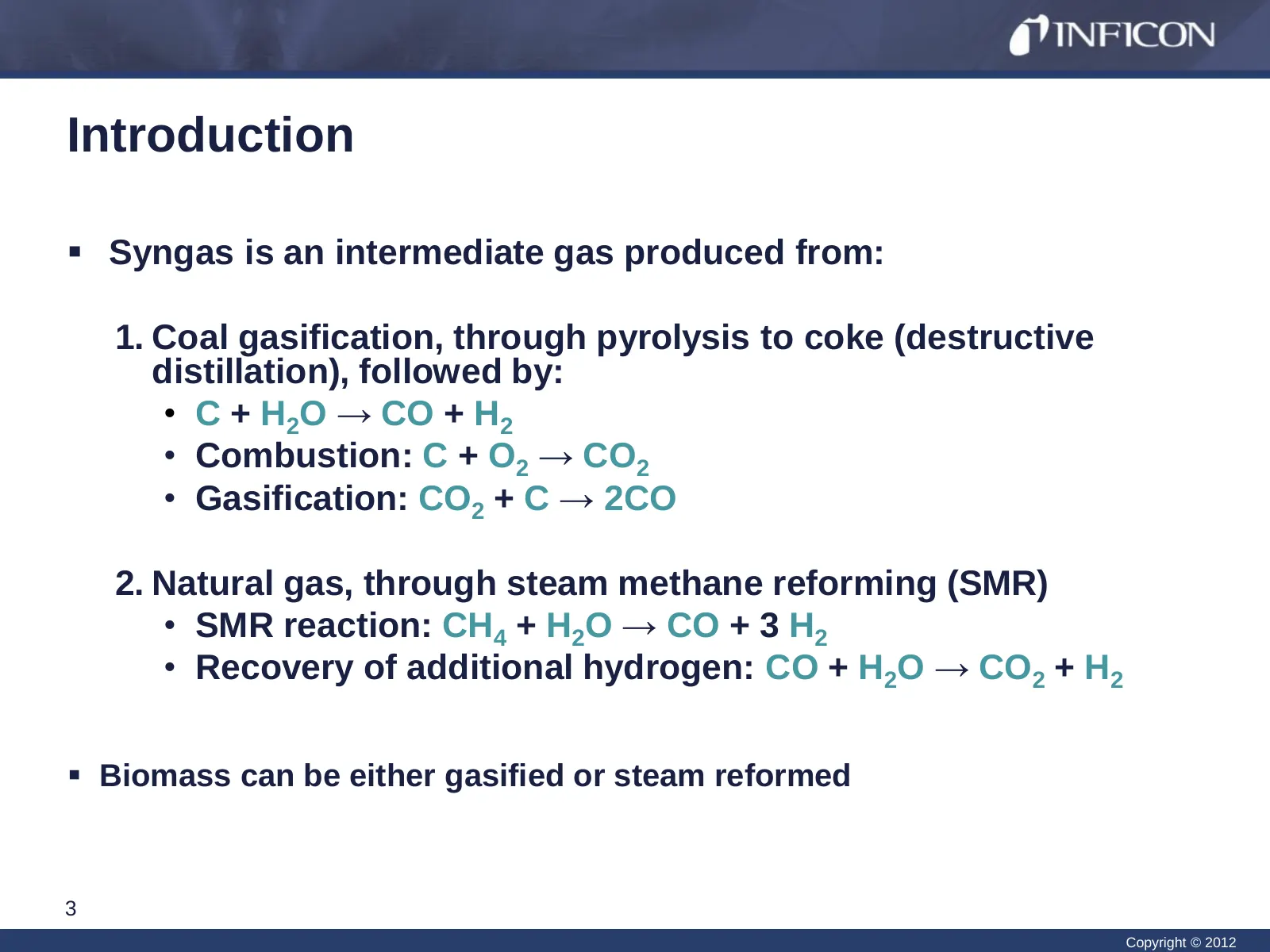
Slide 3: Introduction
Introduction Syngas is an intermediate gas produced from: 1. Coal gasification, through pyrolysis to coke (destructive distillation), followed by: • C + H2O → CO + H2 • Combustion: C + O2 → CO2 • Gasification: CO2 + C → 2CO 2. Natural gas, through steam methane reforming (SMR) • SMR reaction: CH4
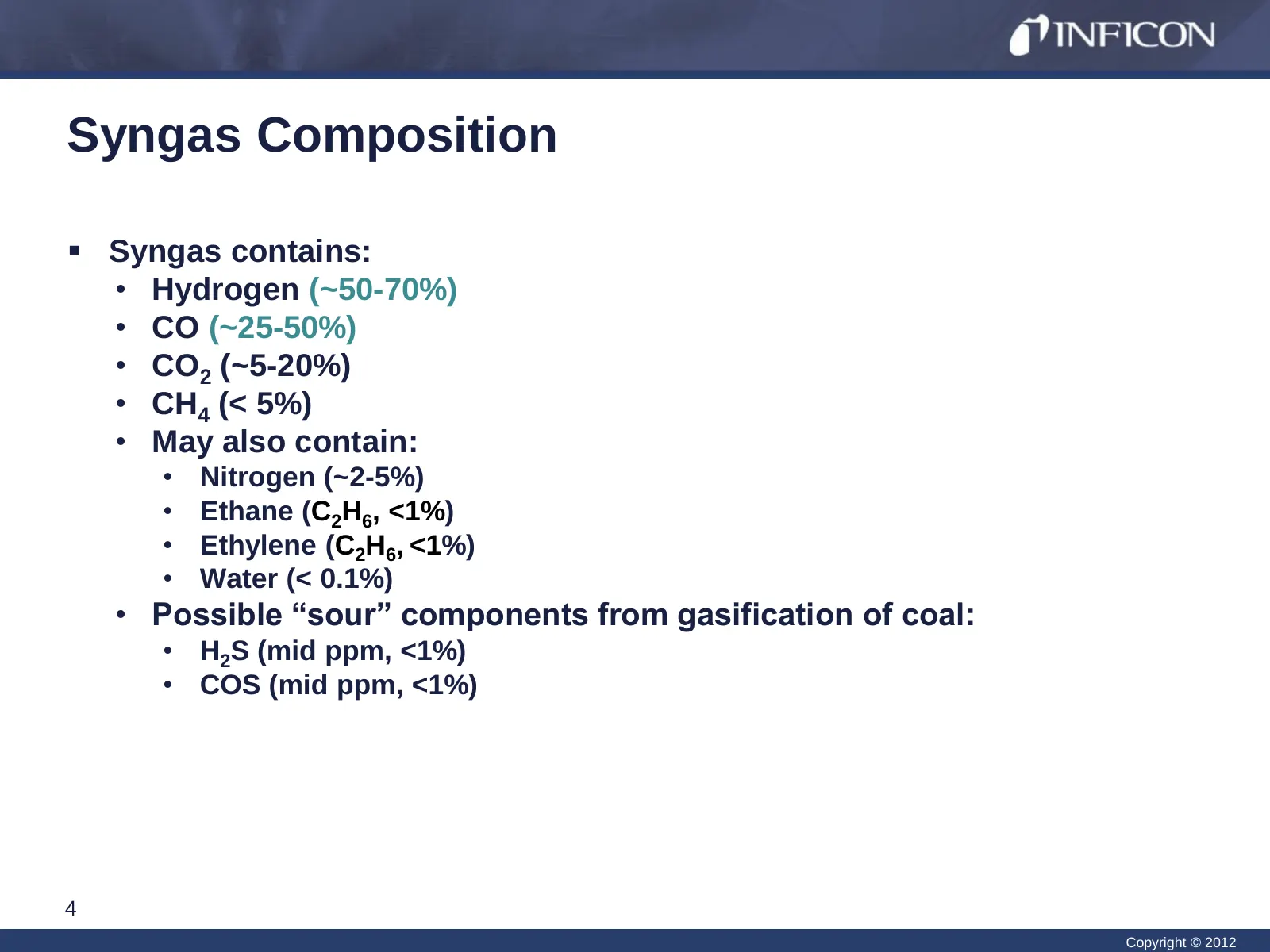
Slide 4: Syngas Composition
Syngas Composition Syngas contains: • Hydrogen (~50-70%) • CO (~25-50%) • CO2 (~5-20%) • CH4 (< 5%) • May also contain: • Nitrogen (~2-5%) • Ethane (C2H6, <1%) • Ethylene (C2H6, <1%) • Water (< 0.1%) • Possible “sour” components from gasification of coal: • H2S (mid ppm, <1%) • COS (mid ppm, <1%)
Slide 5: Syngas Produced from Coal Gasification
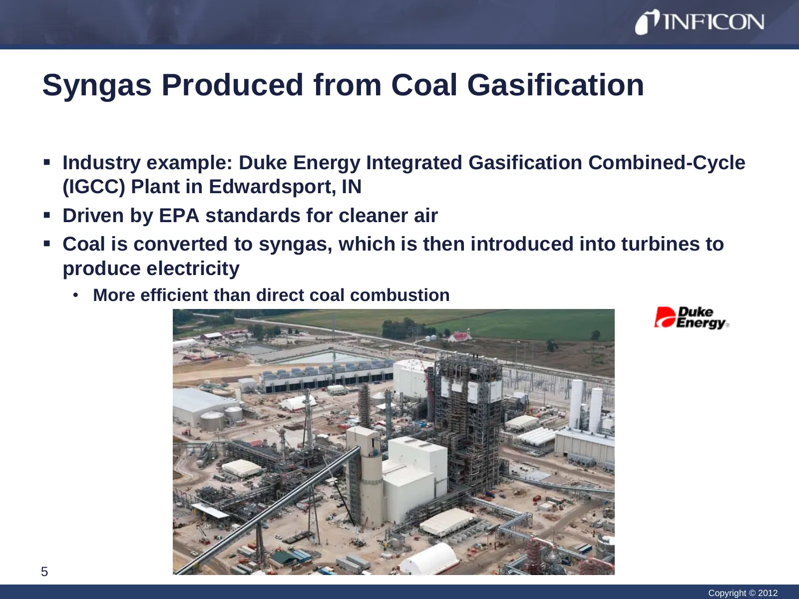
Syngas Produced from Coal Gasification Industry example: Duke Energy Integrated Gasification Combined-Cycle (IGCC) Plant in Edwardsport, IN Driven by EPA standards for cleaner air Coal is converted to syngas, which is then introduced into turbines to produce electricity • More efficient than d
Slide 6: Coal Gasification Environmental Implications
Coal Gasification Environmental Implications Provides 10x more electricity than a traditional energy plant with: • 70% lower sulfur dioxide, nitrogen oxides, and particulates • 30% less water consumption • Produces less solid waste The plant produces elemental sulfur and slag as byproducts, whic
Slide 7: Coal Gasification – Duke Energy Plant
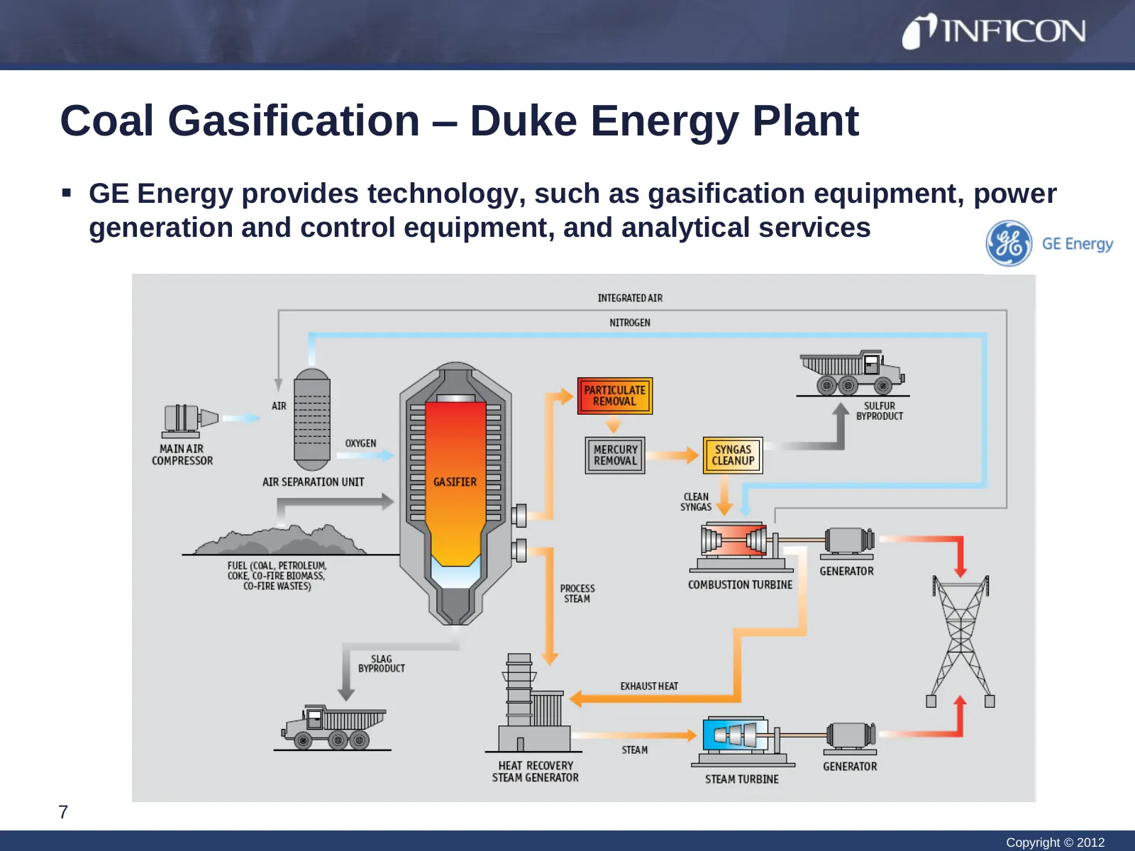
Coal Gasification – Duke Energy Plant GE Energy provides technology, such as gasification equipment, power generation and control equipment, and analytical services 7 Copyright © 2012
Slide 8: Syngas Produced from Natural Gas
Syngas Produced from Natural Gas Steam methane reforming (SMR) is used to produce syngas from stranded (or associated) natural gas that would otherwise be wasted Syngas can be converted, via the Fischer-Tropsch (FT) Process, to higher hydrocarbon synthetic fuels Industry Example: Velocys, Inc.
Slide 9: SMR Environmental Implications
SMR Environmental Implications Utilizes stranded (or associated) natural gas • Approximately 5 trillion cubic feet (TCF) of natural gas is not utilized each year worldwide • Equivalent of 500 million barrels of liquid fuel • The stranded gas can be: • Vented back into the atmosphere • Outlawed bec
Slide 10: SMR Environmental Implications
SMR Environmental Implications Biomass can also be converted to liquid fuels • The US Department of Energy (DOE) estimates that there is enough domestic biomass to replace half of the petroleum-based distillate fuel demand in the US • Considered a renewable energy source • Sources of biomass inclu
Slide 11: Natural Gas to Synthetic Liquid Fuels
Natural Gas to Synthetic Liquid Fuels Steps to produce synthetic fuels from natural gas: 1. Natural gas enters a SMR reactor to generate syngas 2. Syngas is cooled, and water is removed 3. Syngas composition is analyzed 4. Syngas is fed to another reactor and passed over a catalyst to produce synt
Slide 12: Steam Methane Reforming
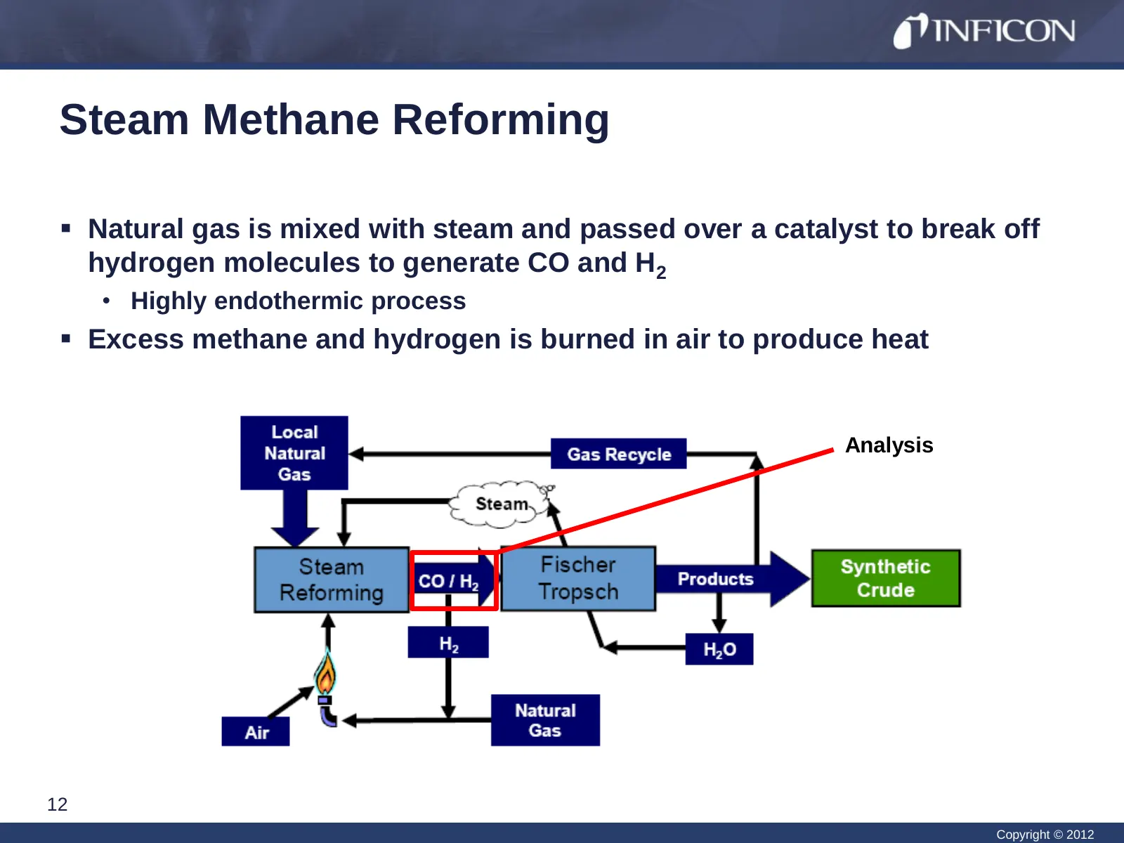
Steam Methane Reforming Natural gas is mixed with steam and passed over a catalyst to break off hydrogen molecules to generate CO and H2 • Highly endothermic process Excess methane and hydrogen is burned in air to produce heat Analysis 12 Copyright © 2012
Slide 13: Syngas Conversion to Synthetic Liquid Fuels
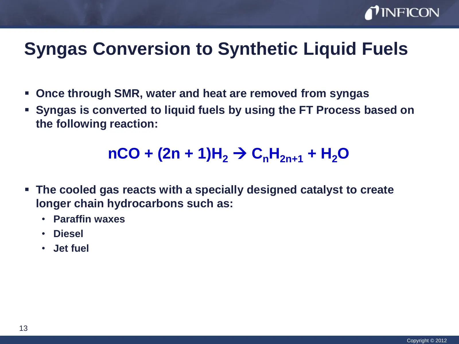
Syngas Conversion to Synthetic Liquid Fuels Once through SMR, water and heat are removed from syngas Syngas is converted to liquid fuels by using the FT Process based on the following reaction: nCO + (2n + 1)H2 CnH2n+1 + H2O The cooled gas reacts with a specially designed catalyst to create
Slide 14: The Need for Precise Analysis
The Need for Precise Analysis Requirements: • Separation and quantification of individual syngas components at the percent level • A total un-normalized concentration (mole %) ranging from 97 to 103% • Analysis of results to optimize the system and maximize productivity • How much methane is being
Slide 15: Gas Chromatography as an Analysis Option
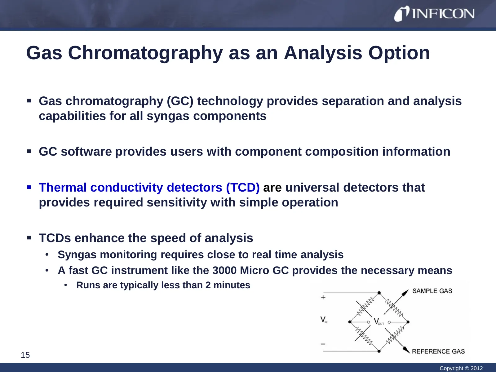
Gas Chromatography as an Analysis Option Gas chromatography (GC) technology provides separation and analysis capabilities for all syngas components GC software provides users with component composition information Thermal conductivity detectors (TCD) are universal detectors that provides requi
Slide 16: Instrumentation
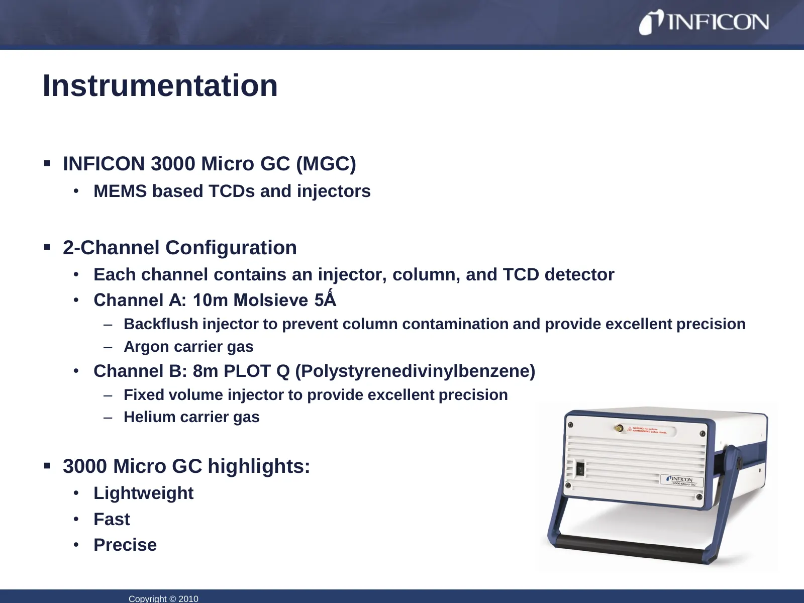
Instrumentation INFICON 3000 Micro GC (MGC) • MEMS based TCDs and injectors 2-Channel Configuration • Each channel contains an injector, column, and TCD detector • Channel A: 10m Molsieve 5Ǻ – Backflush injector to prevent column contamination and provide excellent precision – Argon carrier gas
Slide 17: Calibration Gas Standard - SMR
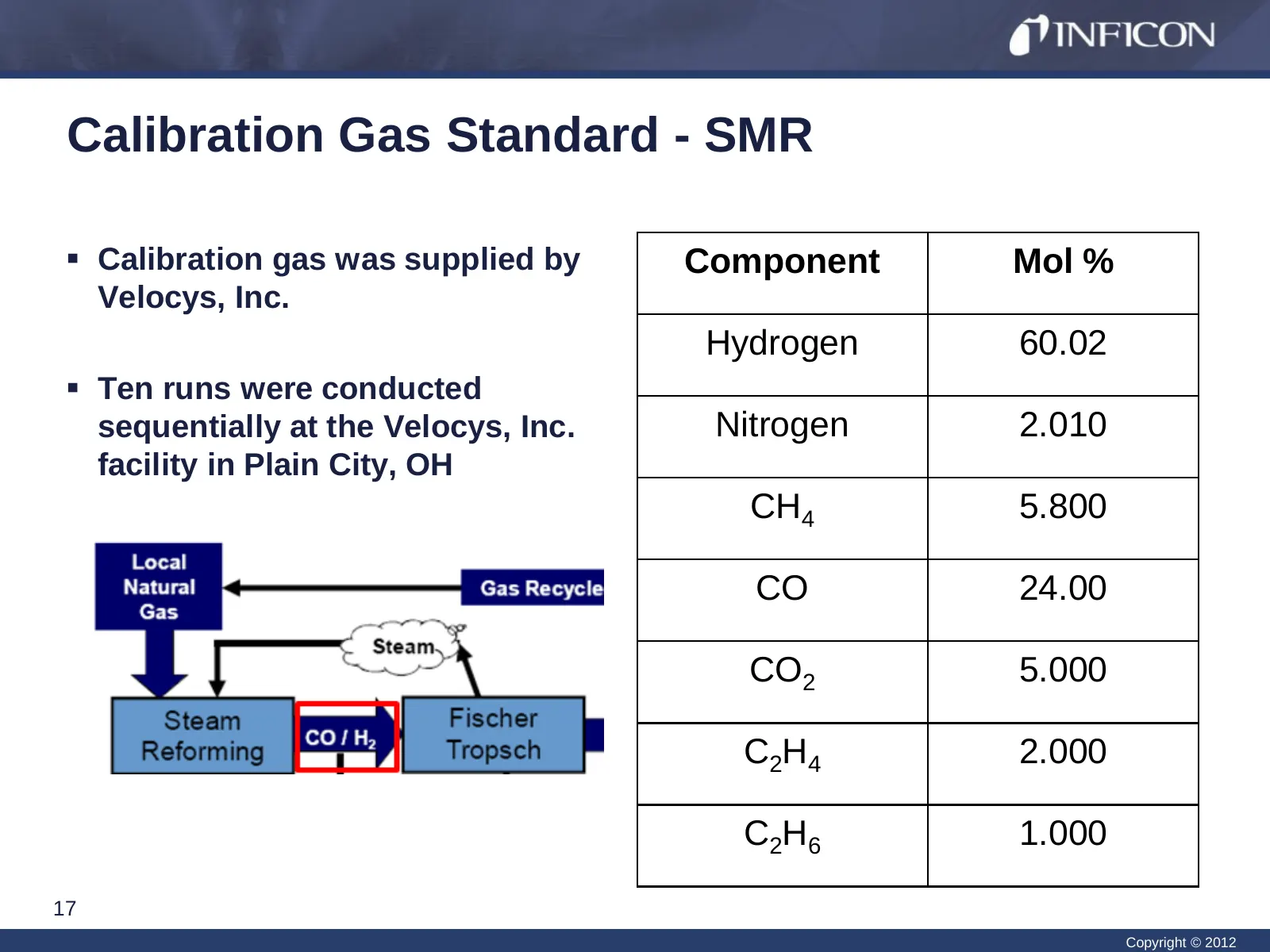
Calibration Gas Standard - SMR Calibration gas was supplied by Component Mol % Velocys, Inc. Hydrogen 60.02 Ten runs were conducted sequentially at the Velocys, Inc. Nitrogen 2.010 facility in Plain City, OH CH4 5.800 CO 24.00 CO2 5.000 C 2H 4 2.000 C 2H 6 1.000 17 Copyright © 2012
Slide 18: 3000 Micro GC Method Parameters
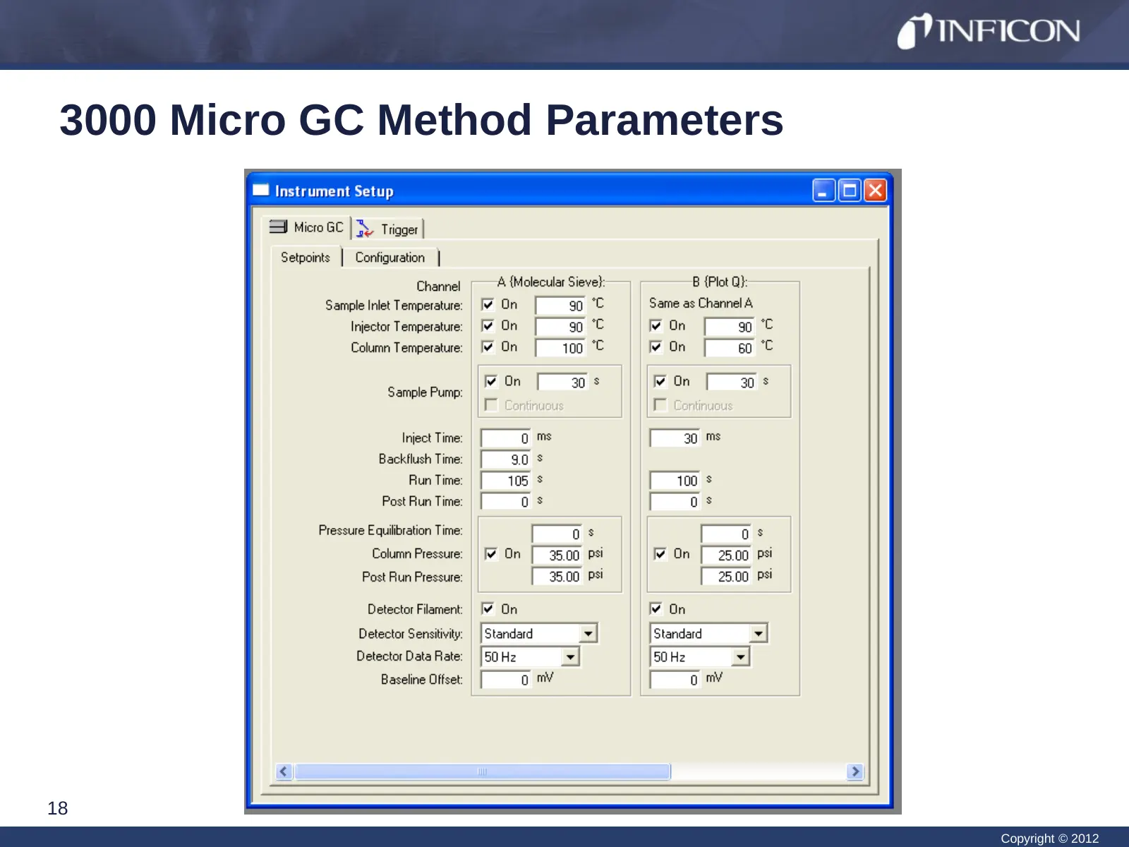
3000 Micro GC Method Parameters 18 Copyright © 2012
Slide 19: Syngas Repeatability Channel A – 10 Runs
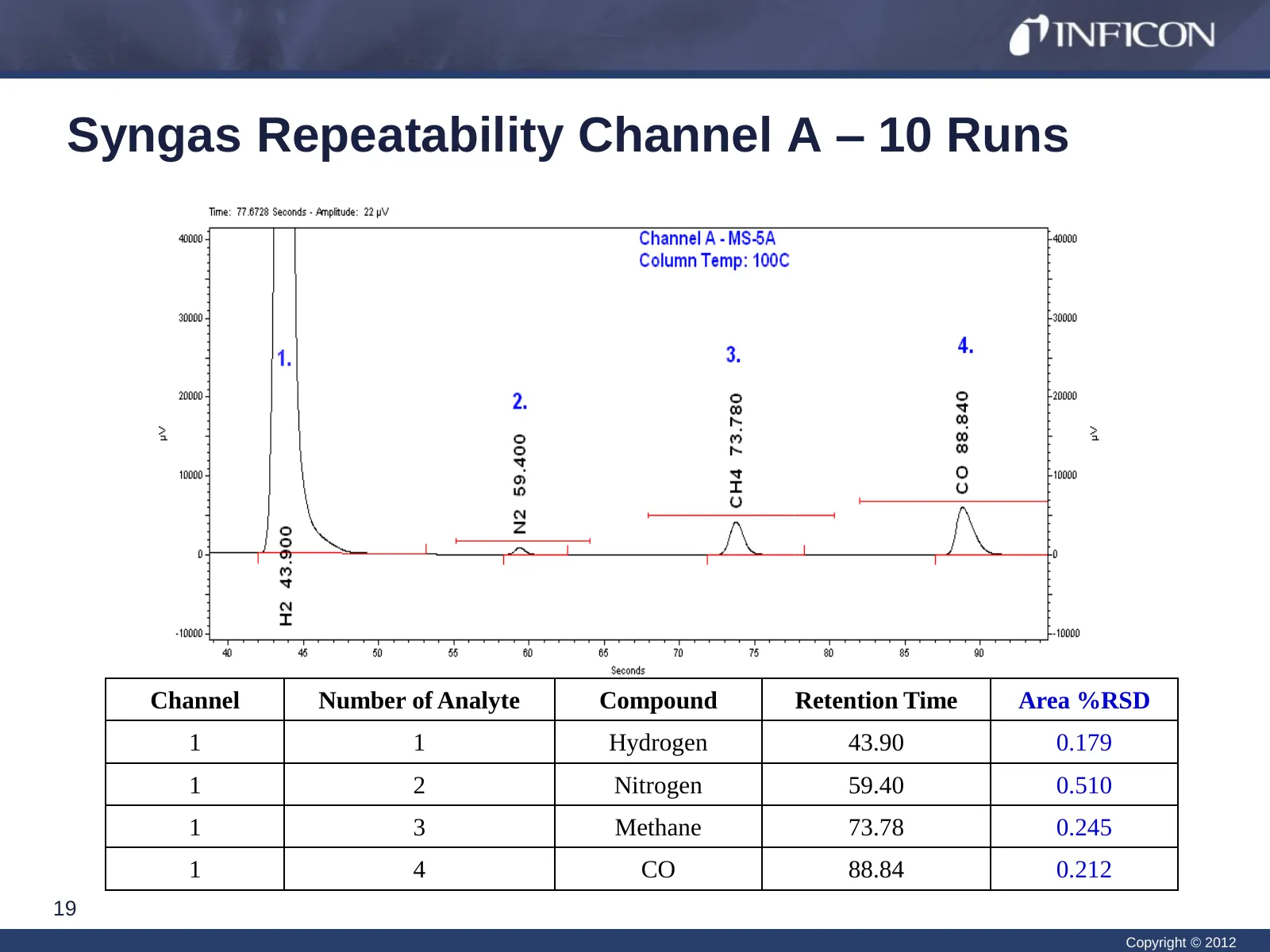
Syngas Repeatability Channel A – 10 Runs Channel Number of Analyte Compound Retention Time Area %RSD 1 1 Hydrogen 43.90 0.179 1 2 Nitrogen 59.40 0.510 1 3 Methane 73.78 0.245 1 4 CO 88.84 0.212 19 Copyright © 2012
Slide 20: Syngas Repeatability Channel B – 10 Runs
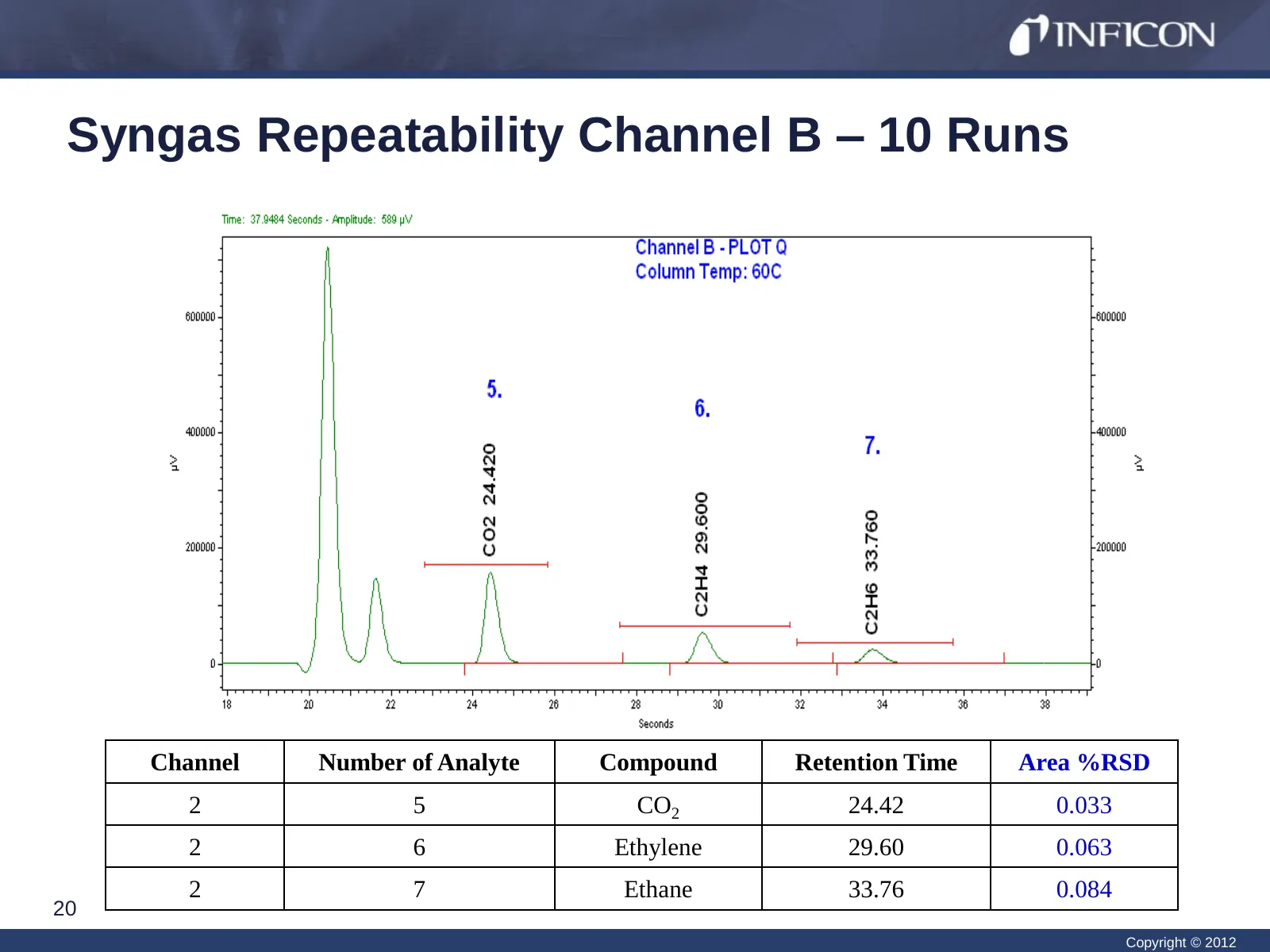
Syngas Repeatability Channel B – 10 Runs Channel Number of Analyte Compound Retention Time Area %RSD 2 5 CO2 24.42 0.033 2 6 Ethylene 29.60 0.063 2 7 Ethane 33.76 0.084 20 Copyright © 2012
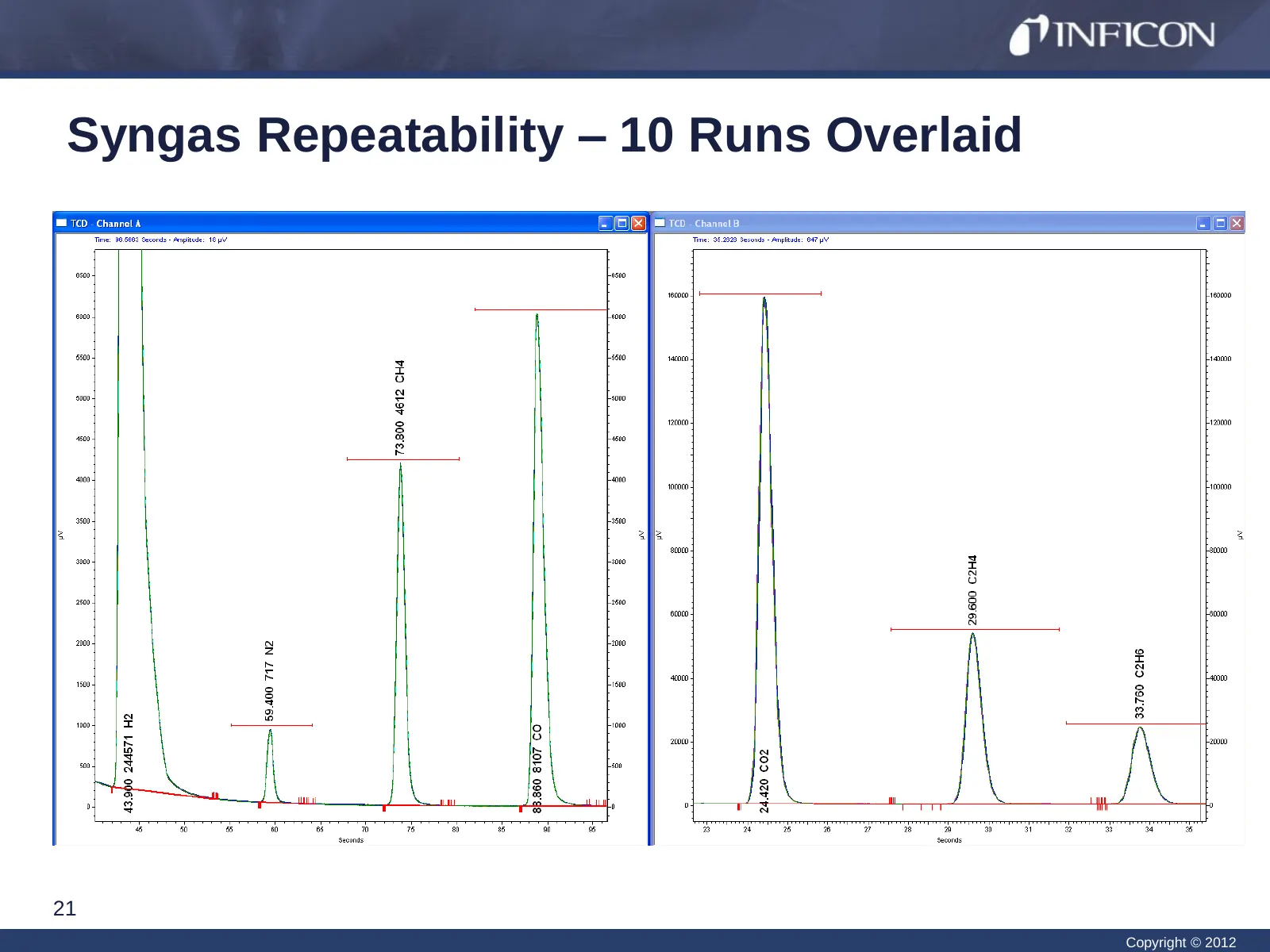
Slide 21: Syngas Repeatability – 10 Runs Overlaid
Syngas Repeatability – 10 Runs Overlaid 21 Copyright © 2012
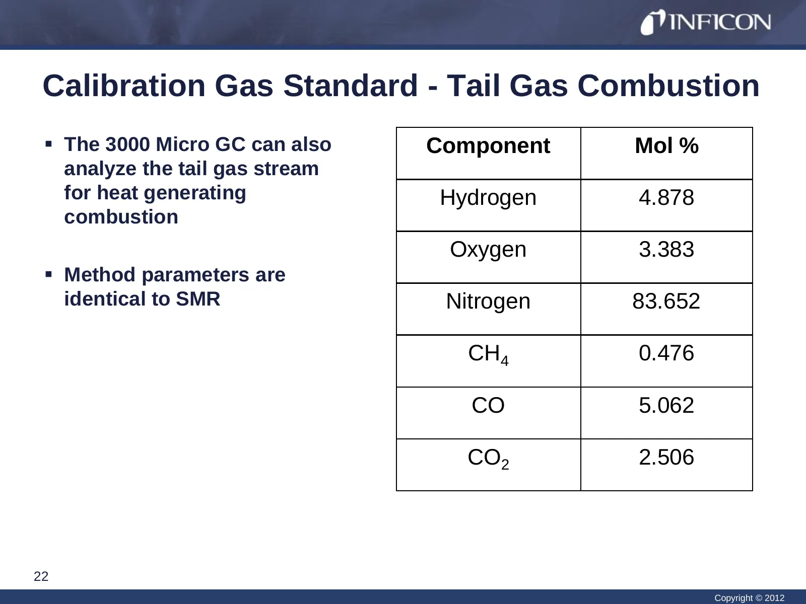
Slide 22: Calibration Gas Standard - Tail Gas Combustion
Calibration Gas Standard - Tail Gas Combustion The 3000 Micro GC can also Component Mol % analyze the tail gas stream for heat generating Hydrogen 4.878 combustion Oxygen 3.383 Method parameters are identical to SMR Nitrogen 83.652 CH4 0.476 CO 5.062 CO2 2.506 22 Copyright © 2012
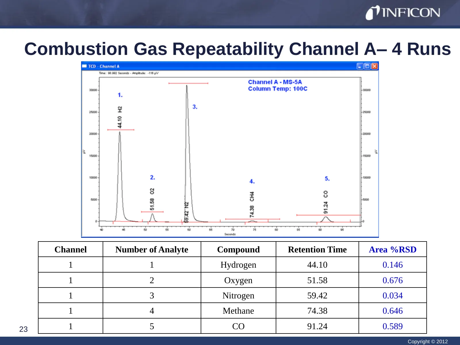
Slide 23: Combustion Gas Repeatability Channel A – 4 Runs
Combustion Gas Repeatability Channel A– 4 Runs Channel Number of Analyte Compound Retention Time Area %RSD 1 1 Hydrogen 44.10 0.146 1 2 Oxygen 51.58 0.676 1 3 Nitrogen 59.42 0.034 1 4 Methane 74.38 0.646 23 1 5 CO 91.24 0.589 Copyright © 2012
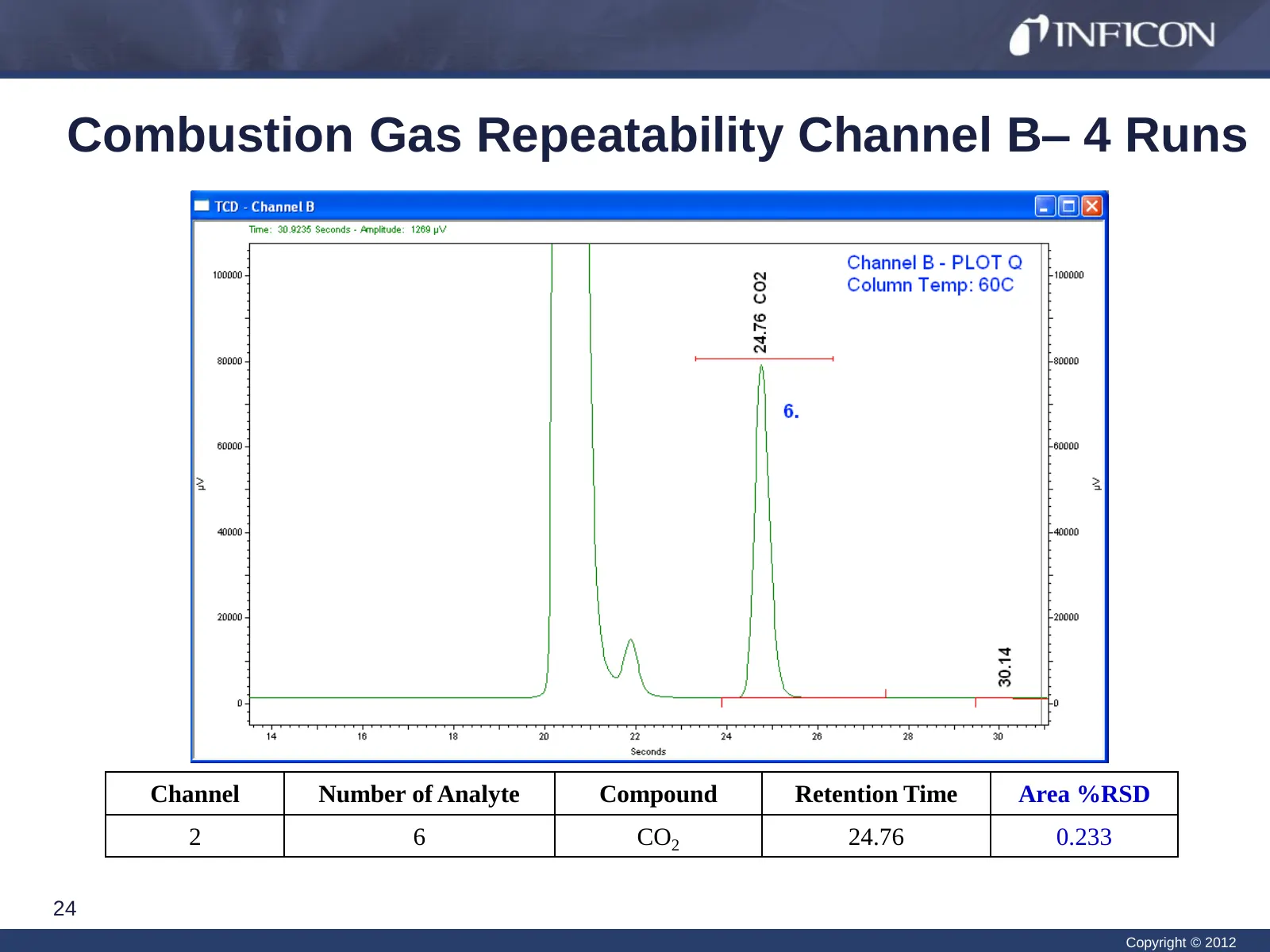
Slide 24: Combustion Gas Repeatability Channel B – 4 Runs
Combustion Gas Repeatability Channel B– 4 Runs Channel Number of Analyte Compound Retention Time Area %RSD 2 6 CO2 24.76 0.233 24 Copyright © 2012
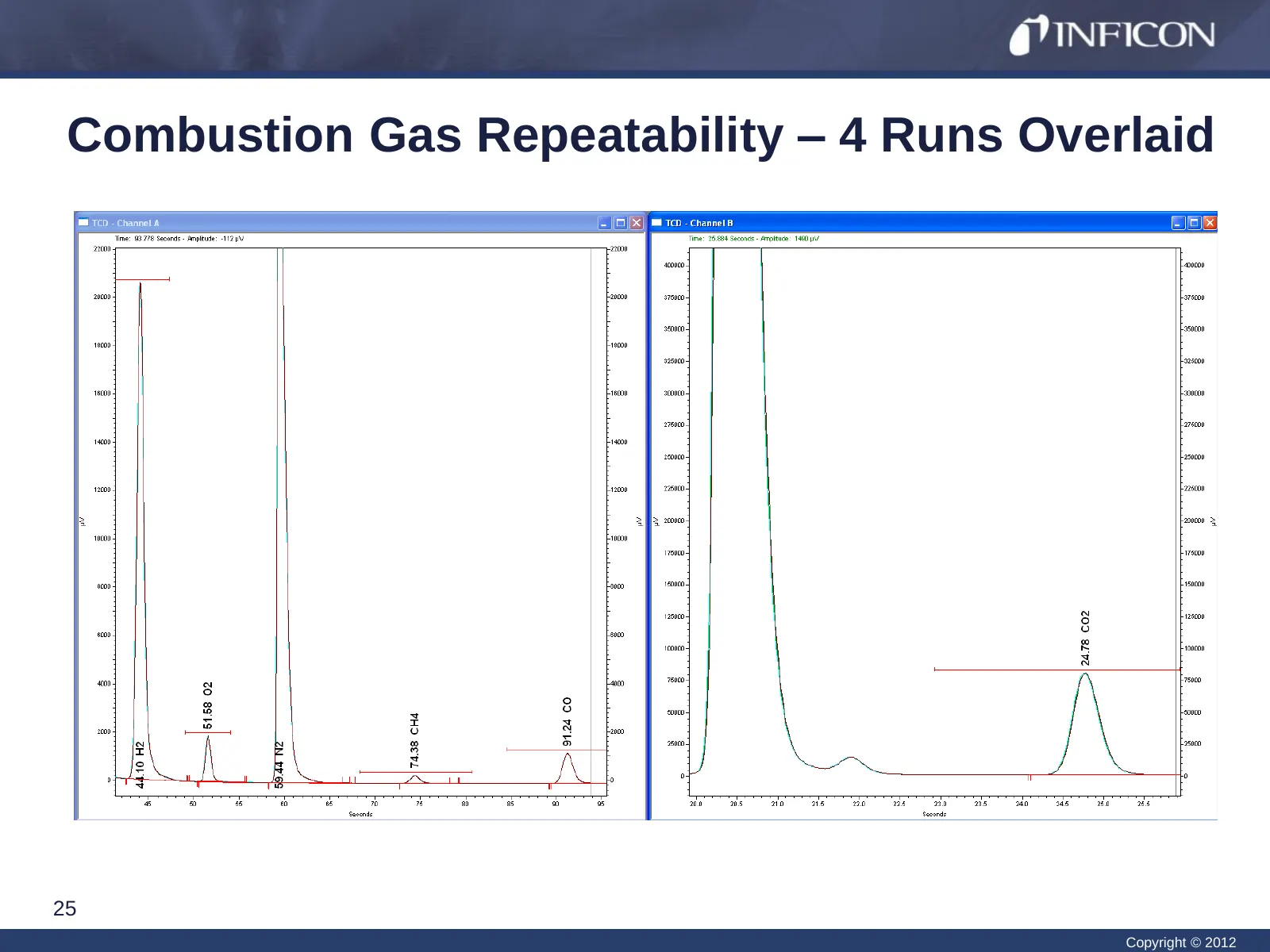
Slide 25: Combustion Gas Repeatability – 4 Runs Overlaid
Combustion Gas Repeatability – 4 Runs Overlaid 25 Copyright © 2012
Slide 26: Conclusion
Conclusion Syngas is an intermediate gas in a series of reactions to generate power or fuel GC technology offers superior analysis for syngas Within 2 minutes, sample are separated and quantified to assist operators in maximizing the efficiency of their technology using the 3000 Micro GC • An
Slide 27: References
References IGCC at a Glance. 2011. http://www.duke-energy.com/pdfs/DukeEnergy_Edwardsport_FactSheet_Sept2011.pdf (accessed January 09, 2012) Edwardsport Integrated Gasification Combined Cycle (IGCC) Station. 2011. http://www.duke-energy.com/pdfs/IGCC-Fact-sheet-12.10.pdf (accessed January 09, 20
Slide 28: Visit booth #320
Visit booth #320 or Visit our website www.INFICON.com for more information 28 Copyright © 2012
Slide 29: Questions?
Questions? 29 Copyright © 2012
Source: Internet Archive copy of inficon.com
More decks from INFICON Holding AG
 Q3 2026 Earnings Presentation18 slides · Oct 27, 2026
 Q2 2026 Earnings Presentation20 slides · Jul 30, 2026
 Q1 2026 Earnings Presentation20 slides · Apr 24, 2026
 Q4 2025 Earnings Presentation32 slides · Mar 24, 2026
 Q1 2025 Earnings Presentation20 slides · Apr 24, 2025
 Technical Presentation (September 2024)44 slides · September 2024