Waters Corporation · NYSE:WAT
Waters — Technical Presentation (October 2016)
52 slides from Waters's technical presentation, Oct 11, 2016
Slide 1: Part I: Polar Compound Retention
Part I: Polar Compound Retention Tuesday, October 11 2016 – 3 pm CET / 9 am EST • Understanding What Works and What Doesn’t Work In Reversed-Phase Polar Compound Retention ©2016 Waters Corporation 1
Slide 2: Overview
Overview Introduction – The Problem Background Challenges for Reversed-Phase HPLC for Polar Molecules Columns for Polar Compound Retention Summary ©2016 Waters Corporation 2
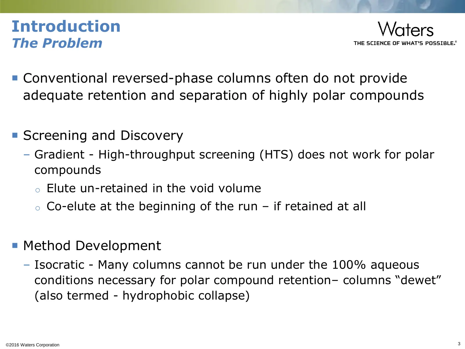
Slide 3: Introduction: The Problem
Introduction The Problem Conventional reversed-phase columns often do not provide adequate retention and separation of highly polar compounds Screening and Discovery – Gradient - High-throughput screening (HTS) does not work for polar compounds o Elute un-retained in the void volume o Co-elute a
Slide 4: Overview
Overview Introduction Background – Polar molecules – Chromatographic methods for retaining polar compounds Challenges for Reversed-Phase HPLC for Polar Molecules Columns for Polar Compound Retention Summary ©2016 Waters Corporation 4
Slide 5: What is a Polar Molecule?
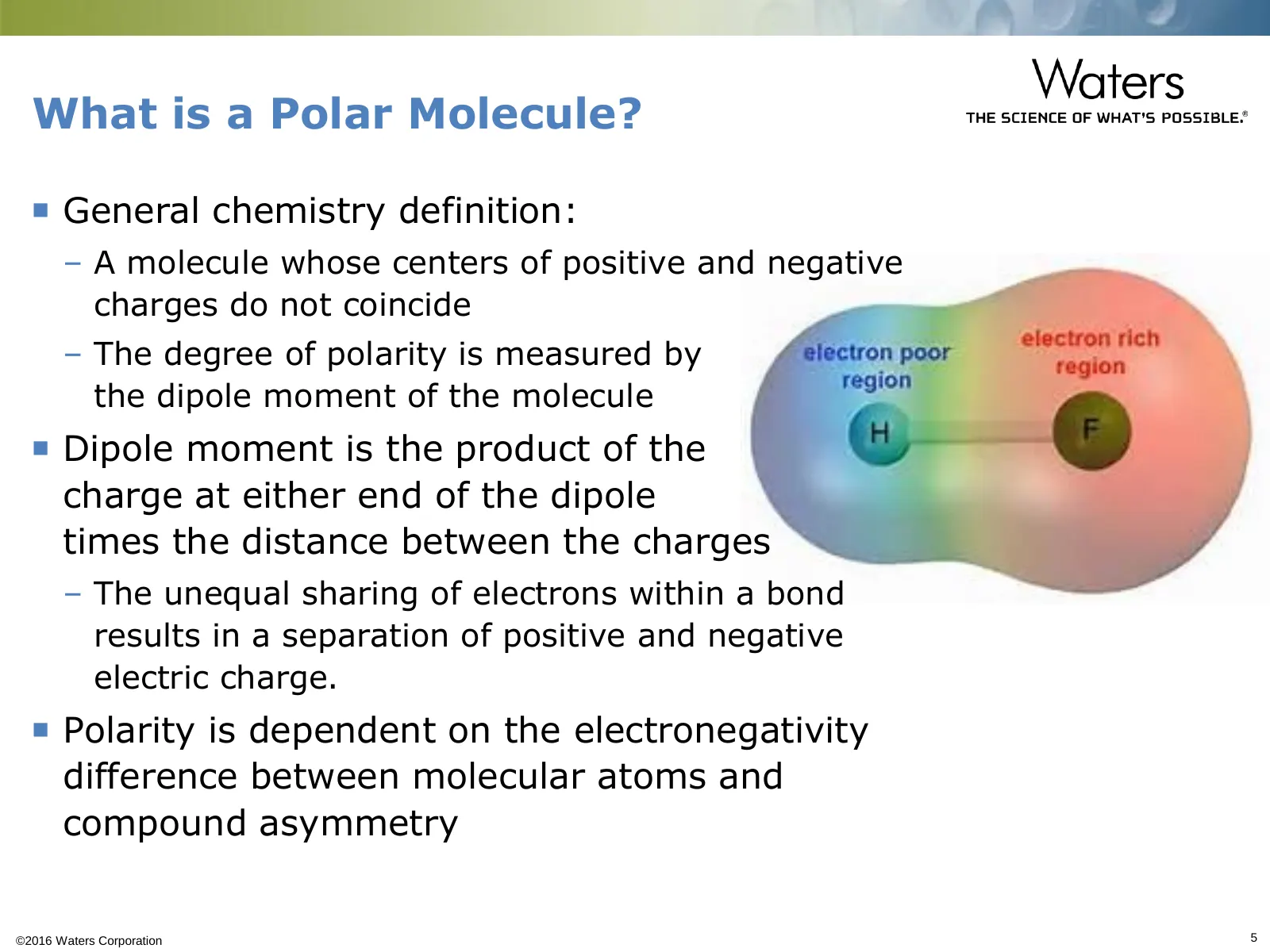
What is a Polar Molecule? General chemistry definition: – A molecule whose centers of positive and negative charges do not coincide – The degree of polarity is measured by the dipole moment of the molecule Dipole moment is the product of the charge at either end of the dipole times the distance
Slide 6: Examples of Polar Organic Molecules
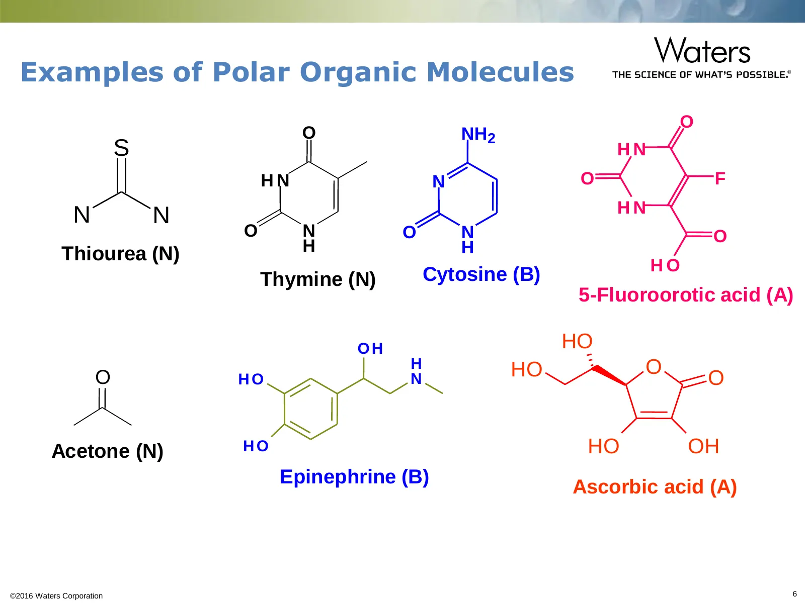
Examples of Polar Organic Molecules O O NH2 S HN HN N O F HN N N O N O N O •Thiourea (N) H H HO Thymine (N) Cytosine (B) 5-Fluoroorotic acid (A) OH HO H HO O O HO N O Acetone (N) HO HO OH Epinephrine (B) Ascorbic acid (A) ©2016 Waters Corporation 6
Slide 7: Comparison of Chromatographic Methods for Retention of Polar Compounds
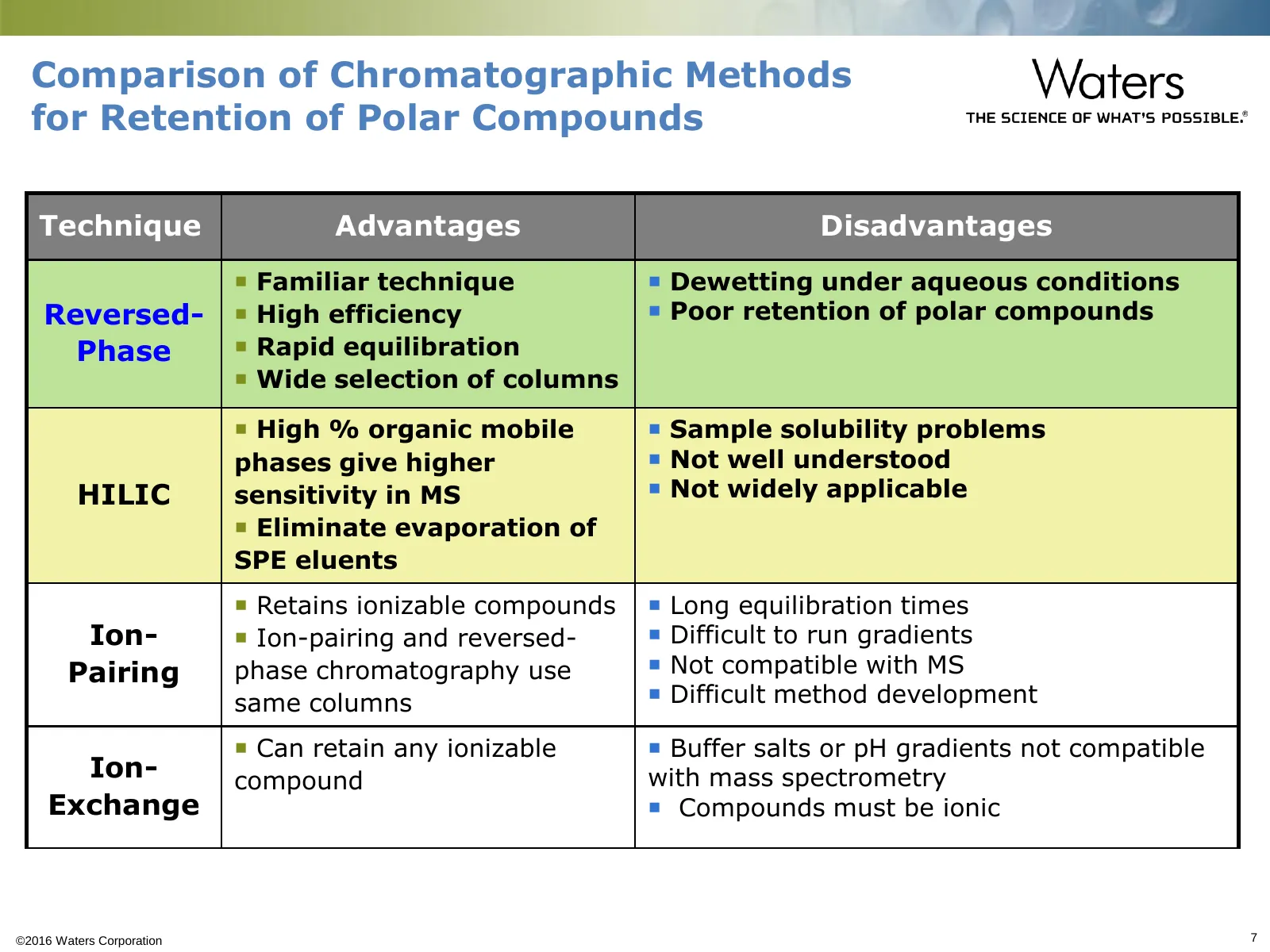
Comparison of Chromatographic Methods for Retention of Polar Compounds Technique Advantages Disadvantages Familiar technique Dewetting under aqueous conditions Reversed- High efficiency Poor retention of polar compounds Phase Rapid equilibration Wide selection of columns High % organic
Slide 8: Overview
Overview Introduction Background Challenges for Reversed-Phase HPLC for Polar Molecules – What is Dewetting – What does not work for Polar Compound Retention Columns for Polar Compound Retention Summary ©2016 Waters Corporation 8
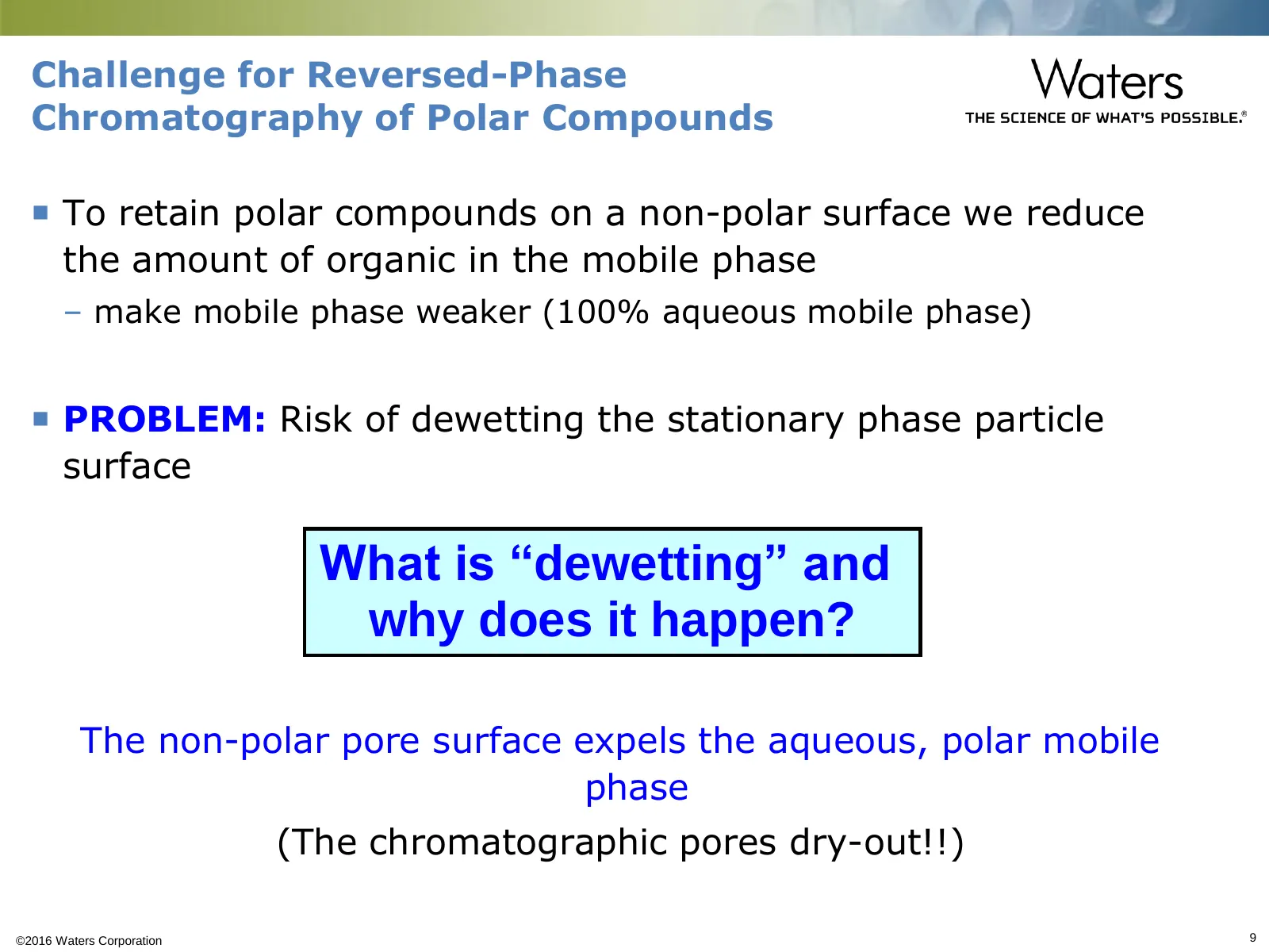
Slide 9: What is dewetting and Challenge for Reversed-Phase Chromatography
Challenge for Reversed-Phase Chromatography of Polar Compounds To retain polar compounds on a non-polar surface we reduce the amount of organic in the mobile phase – make mobile phase weaker (100% aqueous mobile phase) PROBLEM: Risk of dewetting the stationary phase particle surface What is “dew
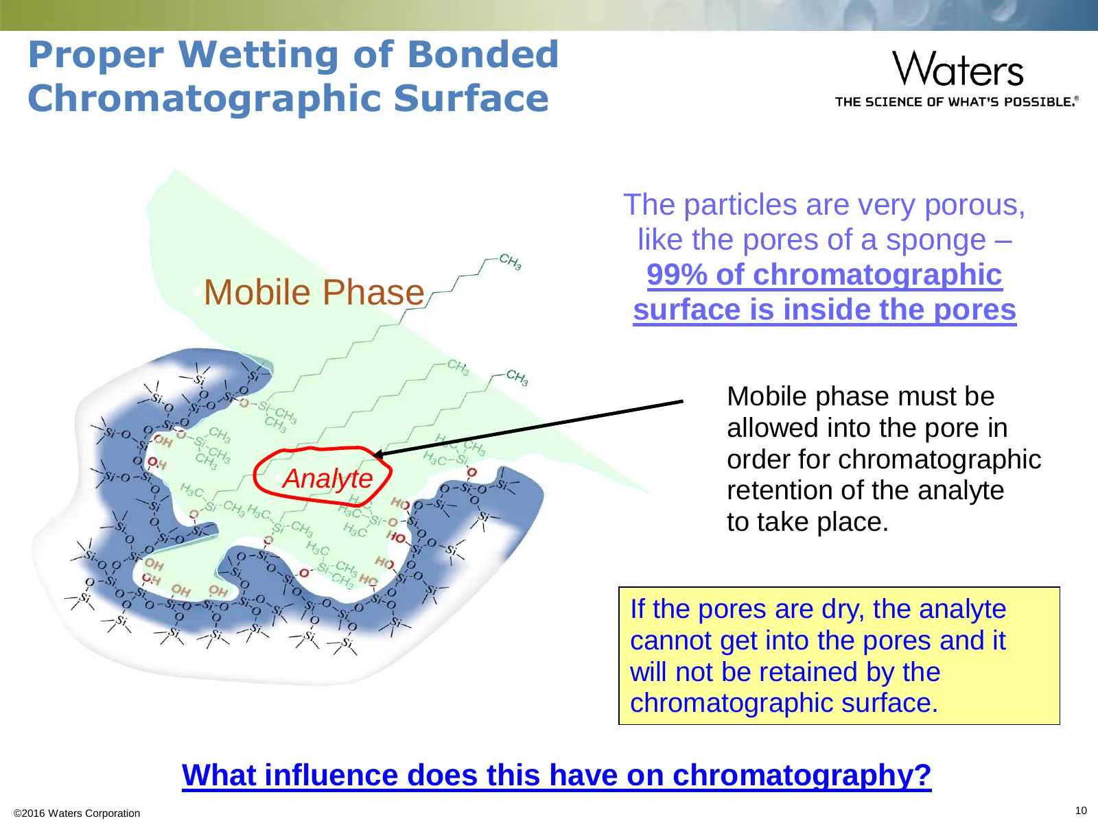
Slide 10: Proper Wetting of Bonded Chromatographic Surface
Proper Wetting of Bonded Chromatographic Surface The particles are very porous, like the pores of a sponge – 99% of chromatographic •Mobile Phase surface is inside the pores Mobile phase must be allowed into the pore in order for chromatographic •Analyte retention of the analyte to take place. If th
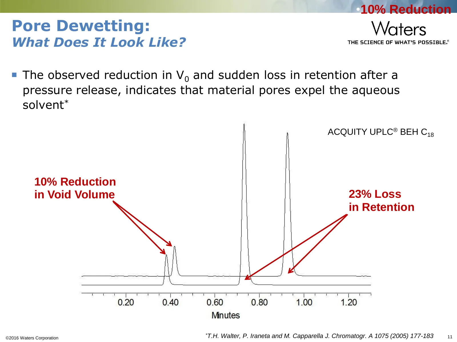
Slide 11: Pore Dewetting: What Does It Look Like?
•10% Reduction Pore Dewetting: What Does It Look Like? The observed reduction in V0 and sudden loss in retention after a pressure release, indicates that material pores expel the aqueous solvent* •ACQUITY UPLC® BEH C18 •10% Reduction •in Void Volume •23% Loss •in Retention ©2016 Waters Corporation
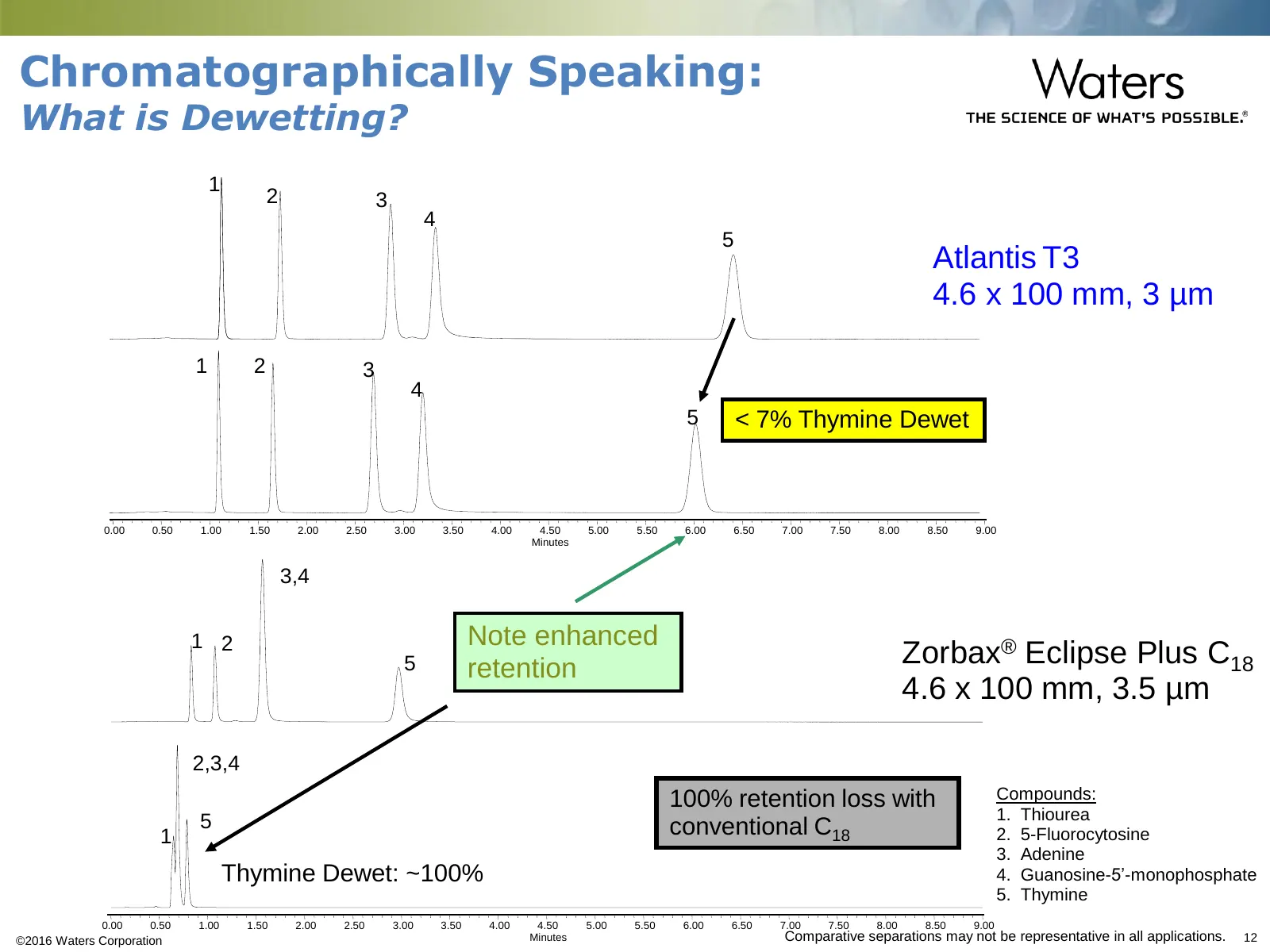
Slide 12: Chromatographically Speaking: What is Dewetting?
Chromatographically Speaking: What is Dewetting? •1 •2 •3 •4 •5 •Atlantis T3 •4.6 x 100 mm, 3 µm •1 •2 •3 •4 •5 < 7% Thymine Dewet •0.00 •0.50 •1.00 •1.50 •2.00 •2.50 •3.00 •3.50 •4.00 •4.50 •5.00 •5.50 •6.00 •6.50 •7.00 •7.50 •8.00 •8.50 •9.00 •Minutes •3,4 •1 •2 Note enhanced •5 retention •Zorbax®
Slide 13: Conventional C18 Column Dewetting
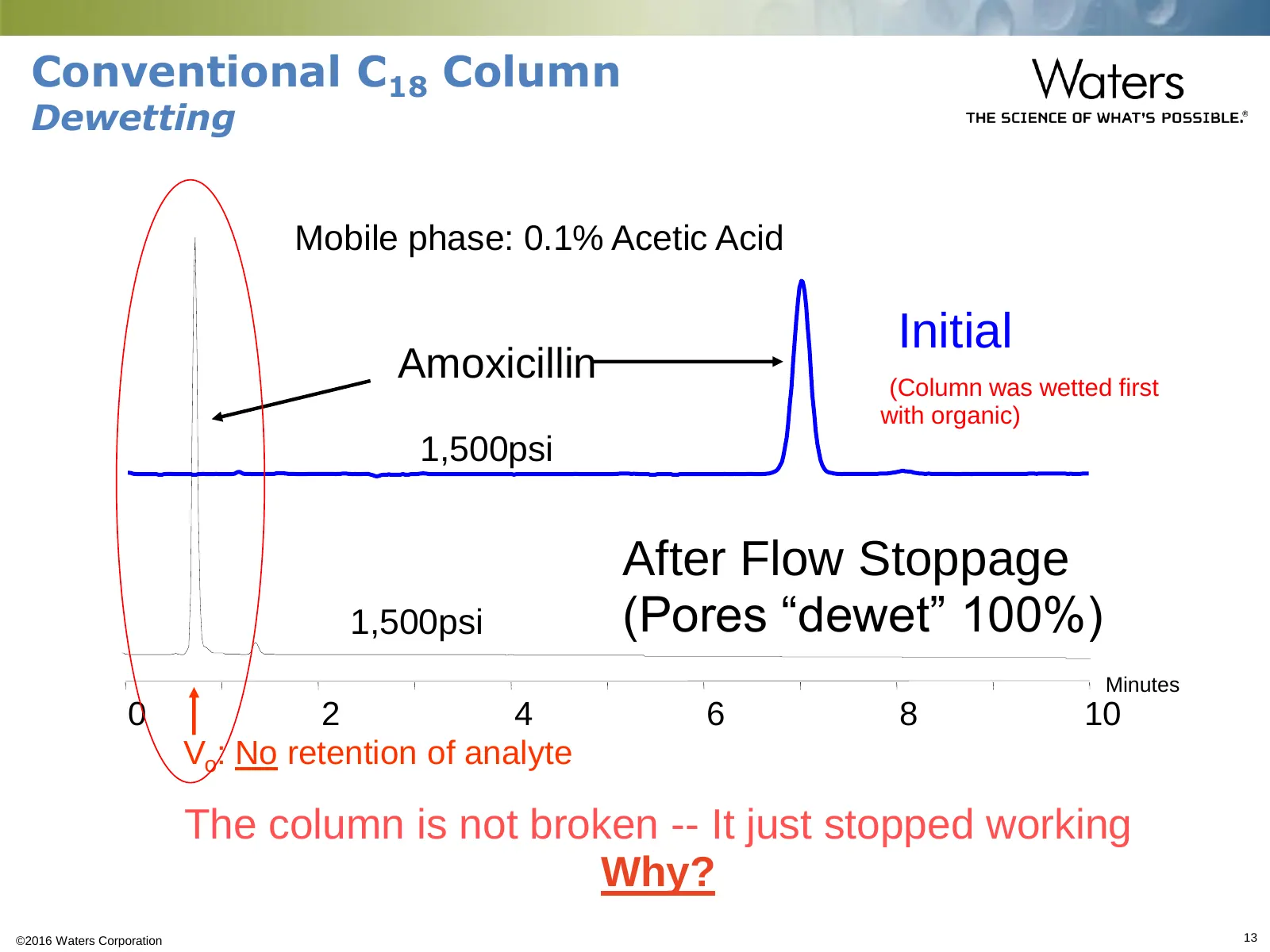
Conventional C18 Column Dewetting •Mobile phase: 0.1% Acetic Acid •Initial •Amoxicillin •(Column was wetted first with organic) •1,500psi •After Flow Stoppage •1,500psi •(Pores “dewet” 100%) •Minutes •0 •2 •4 •6 •8 •10 •Vo: No retention of analyte •The column is not broken -- It just stopped working
Slide 14: Pore Dewetting Mechanism
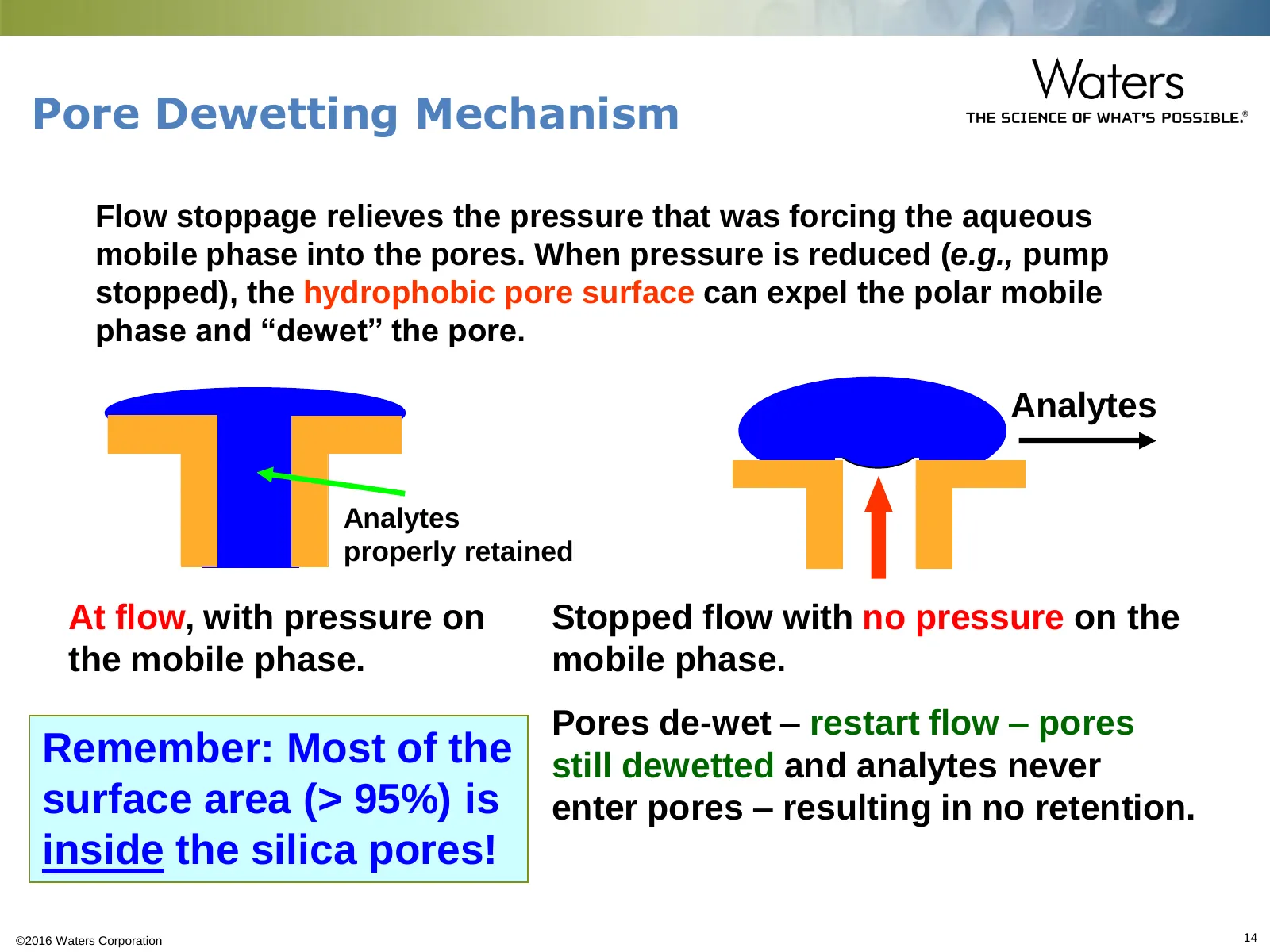
Pore Dewetting Mechanism Flow stoppage relieves the pressure that was forcing the aqueous mobile phase into the pores. When pressure is reduced (e.g., pump stopped), the hydrophobic pore surface can expel the polar mobile phase and “dewet” the pore. Analytes Analytes properly retained At flow, with
Slide 15: Stationary Phase Wetting/Dewetting
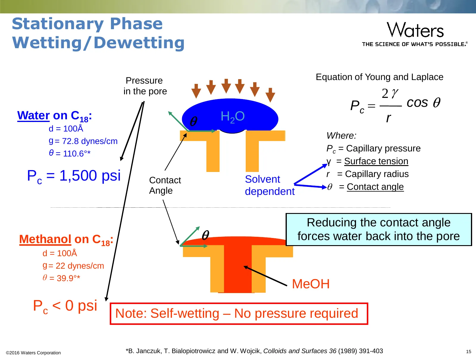
Stationary Phase Wetting/Dewetting •Pressure Equation of Young and Laplace •in the pore 2g Pc = cos q Water on C18: q H 2O r d = 100Å g = 72.8 dynes/cm Where: θ = 110.6°* Pc = Capillary pressure γ = Surface tension Pc = 1,500 psi Contact Solvent r = Capillary radius Angle q = Contact angle dependent
Slide 16: Re-wetting a Stationary Phase
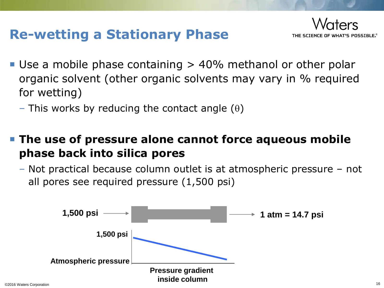
Re-wetting a Stationary Phase Use a mobile phase containing > 40% methanol or other polar organic solvent (other organic solvents may vary in % required for wetting) – This works by reducing the contact angle (q) The use of pressure alone cannot force aqueous mobile phase back into silica pores
Slide 17: Dewetting Summary
Dewetting Summary Dewetting - not “hydrophobic collapse” causes the sudden loss of retention under highly aqueous conditions V0 reduction and sudden loss in retention after a pressure drop indicate that the pores expel aqueous solvent (vs. ligand chains “folding” or “matting” as described by hyd
Slide 18: Embedded Polar Groups: What Doesn't Work
Embedded Polar Groups: What Doesn’t Work Embedded polar group columns designed to: – Improve peak shapes for basic compounds – Provide complementary selectivity as compared to straight- chain alkyl stationary phases Examples of embedded polar groups include carbamate, ether, amide, urea, etc.
Slide 19: Embedded Polar Groups: What Doesn't Work
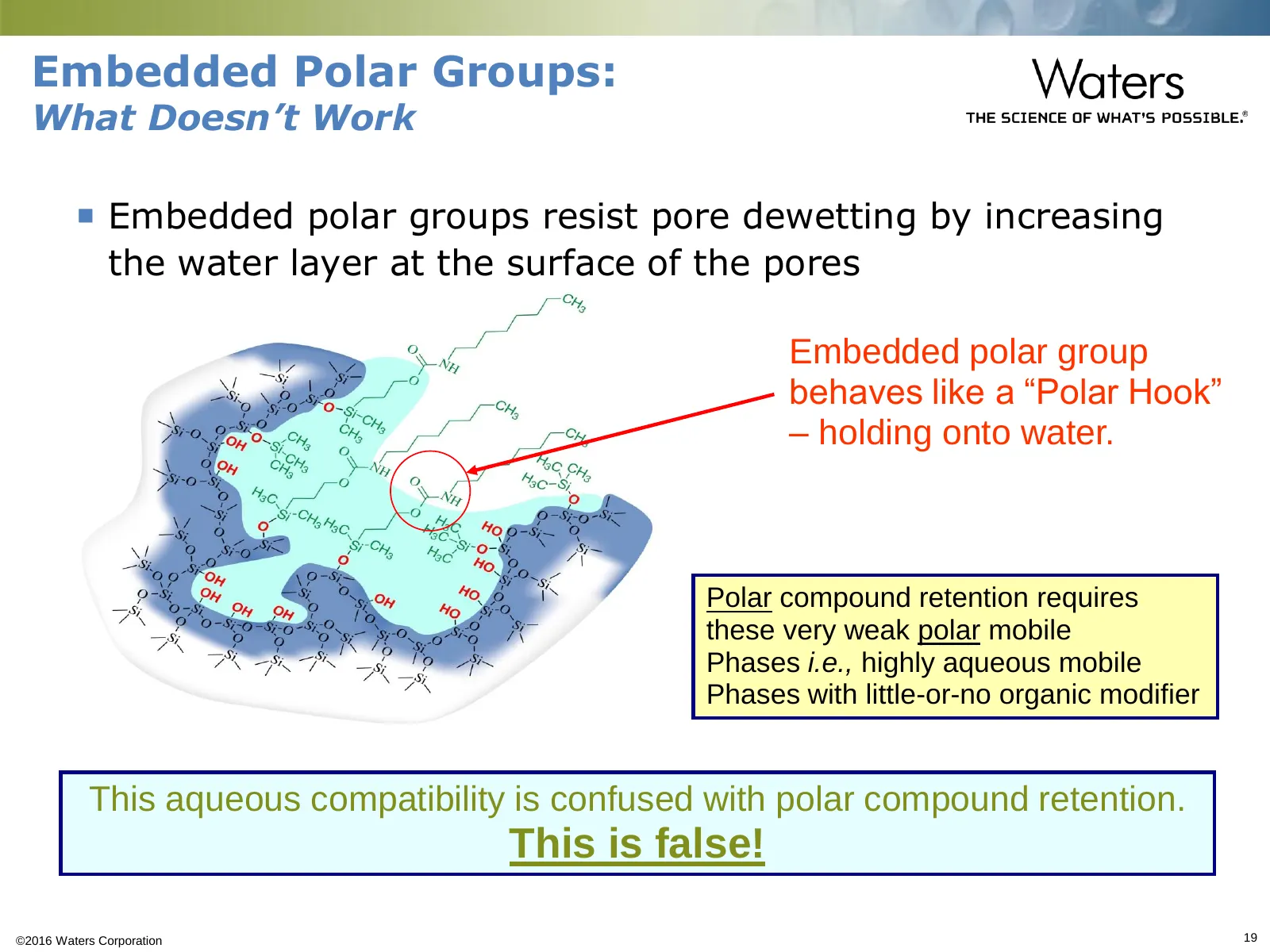
Embedded Polar Groups: What Doesn’t Work Embedded polar groups resist pore dewetting by increasing the water layer at the surface of the pores Embedded polar group behaves like a “Polar Hook” – holding onto water. Polar compound retention requires these very weak polar mobile Phases i.e., highly a
Slide 20: Embedded Polar Groups: What Doesn't Work
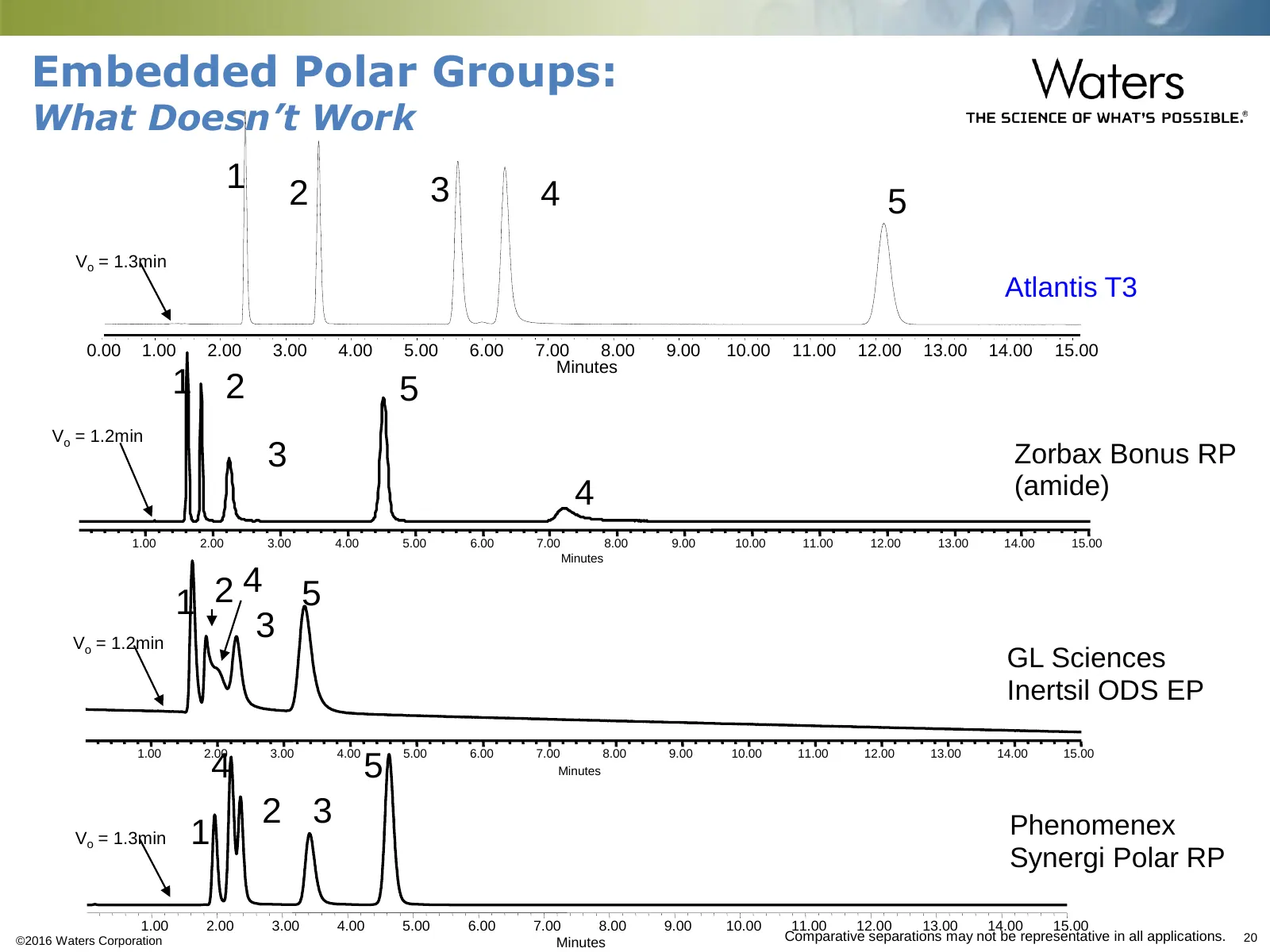
Embedded Polar Groups: What Doesn’t Work •1 •2 •3 •4 •5 •Vo = 1.3min Atlantis T3 •0.00 •1.00 •2.00 •3.00 •4.00 •5.00 •6.00 •7.00 •8.00 •9.00 •10.00 •11.00 •12.00 •13.00 •14.00 •15.00 •Minutes •1 •2 •5 •Vo = 1.2min •3 Zorbax Bonus RP •4 (amide) •1.00 •2.00 •3.00 •4.00 •5.00 •6.00 •7.00 •8.00 •9.00 •1
Slide 21: Embedded Polar Groups – What Doesn't Work
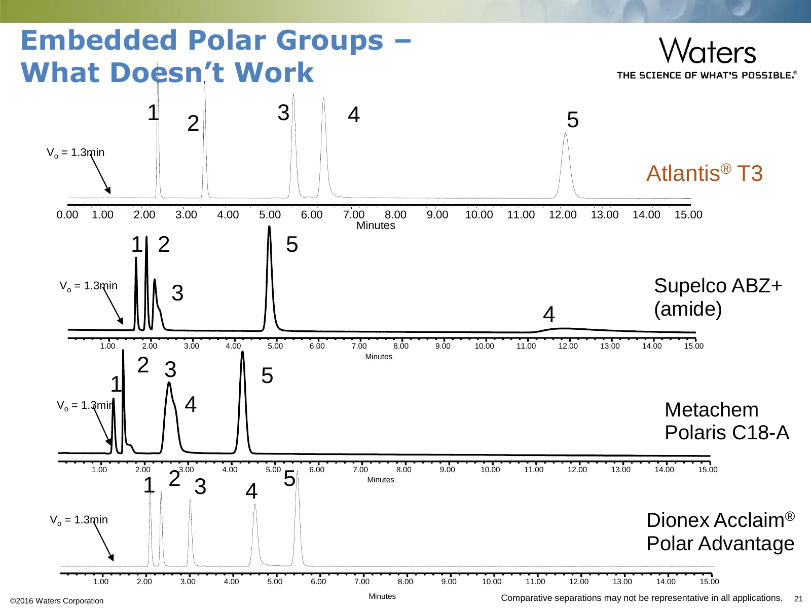
Embedded Polar Groups – What Doesn’t Work •1 •2 •3 •4 •5 •Vo = 1.3min •Atlantis® T3 •0.00 •1.00 •2.00 •3.00 •4.00 •5.00 •6.00 •7.00 •8.00 •9.00 •10.00 •11.00 •12.00 •13.00 •14.00 •15.00 •Minutes •1 •2 •5 •Vo = 1.3min •3 •Supelco ABZ+ •4 •(amide) •1.00 •2.00 •3.00 •4.00 •5.00 •6.00 •7.00 •8.00 •9.00
Slide 22: Embedded Polar Groups: What Doesn't Work
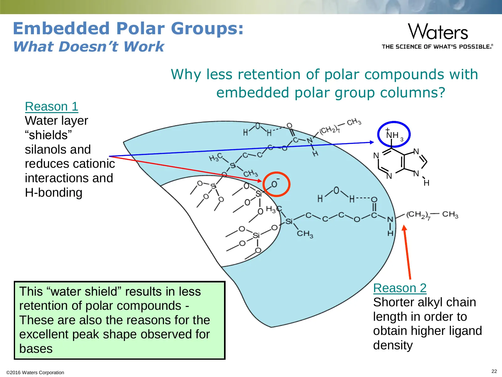
Embedded Polar Groups: What Doesn’t Work Why less retention of polar compounds with embedded polar group columns? Reason 1 Water layer + “shields” NH 3 silanols and N N reduces cationic N N interactions and H H-bonding This “water shield” results in less Reason 2 retention of polar compounds - Short
Slide 23: Embedded Polar Groups: Not the Answer
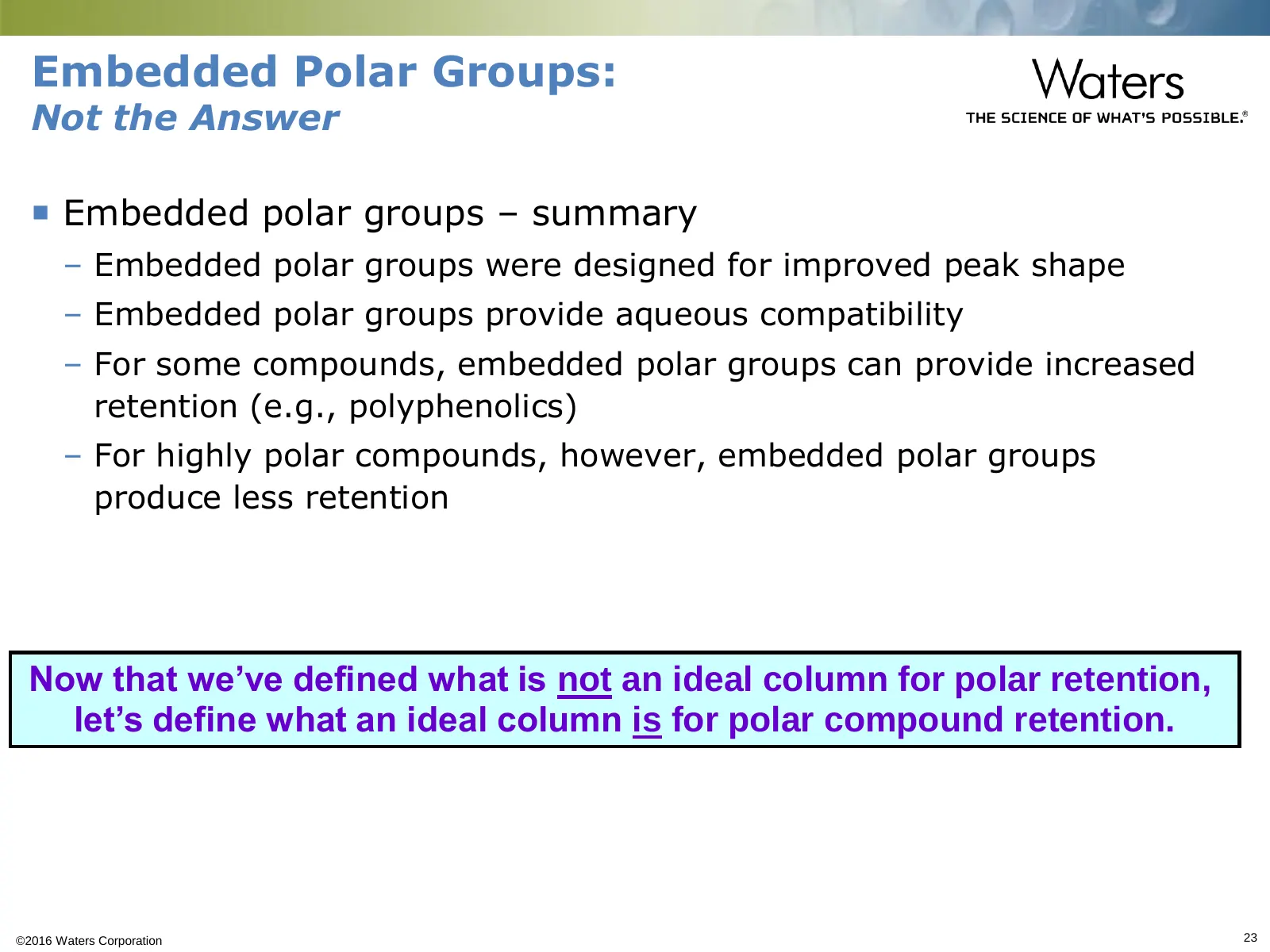
Embedded Polar Groups: Not the Answer Embedded polar groups – summary – Embedded polar groups were designed for improved peak shape – Embedded polar groups provide aqueous compatibility – For some compounds, embedded polar groups can provide increased retention (e.g., polyphenolics) – For highly p
Slide 24: Overview
Overview Introduction Background Challenges for Reversed-Phase HPLC for Polar Molecules Columns for Polar Compound Retention – Designing the ideal column – Particle and Bonding Considerations – Introduction to the T3 Column Family Summary ©2016 Waters Corporation 24
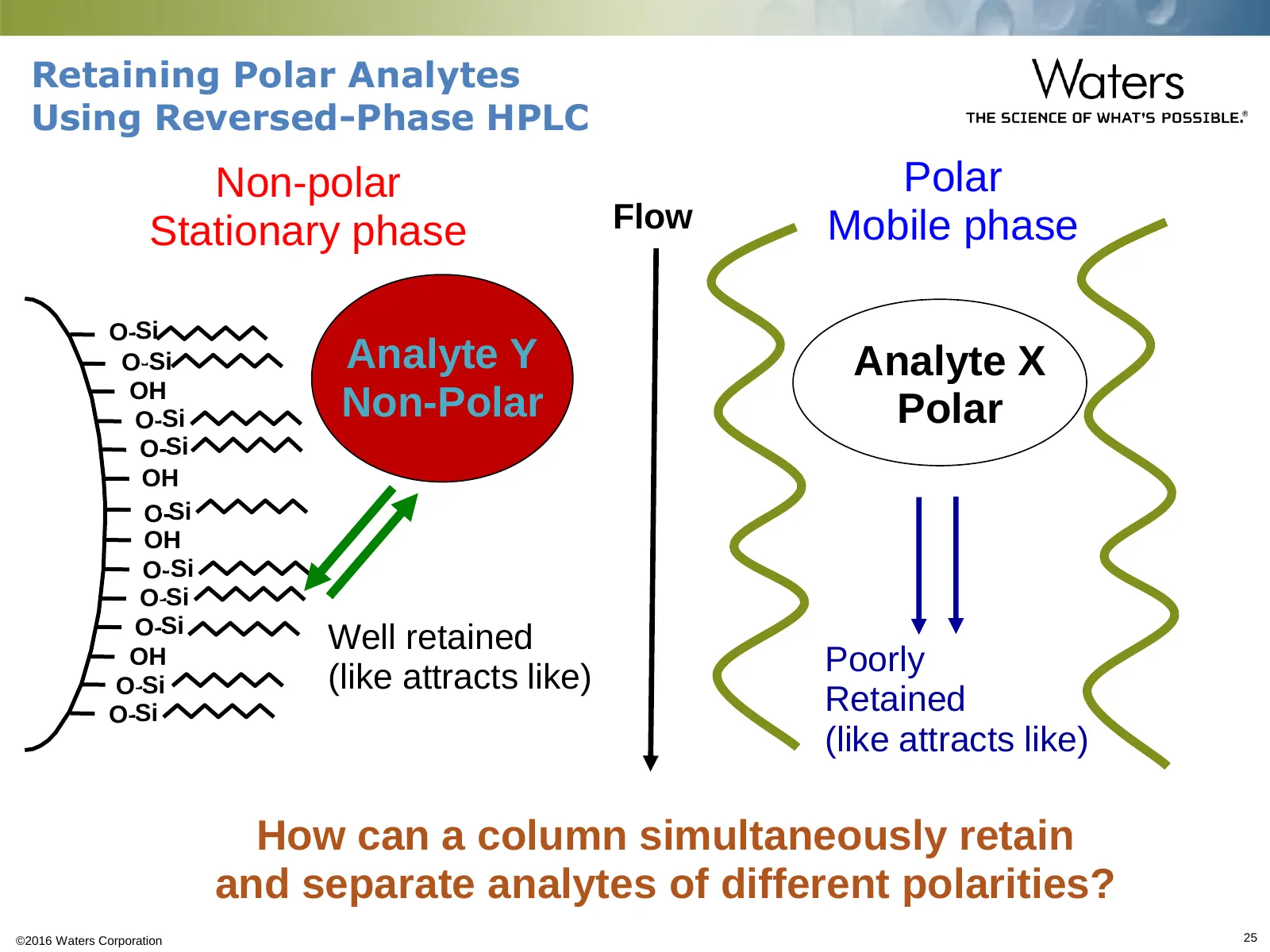
Slide 25: Retaining Polar Analytes Using Reversed-Phase HPLC
Retaining Polar Analytes Using Reversed-Phase HPLC •Non-polar •Polar •Stationary phase •Flow •Mobile phase •O-•Si •O-•Si Analyte Y •Analyte X •OH •O-•Si Non-Polar •Polar •O-•Si •OH •O-•Si •OH •O-•Si •O-•Si •O-•Si •Well retained •OH •Poorly •O-•Si •(like attracts like) •O-•Si •Retained •(like attract
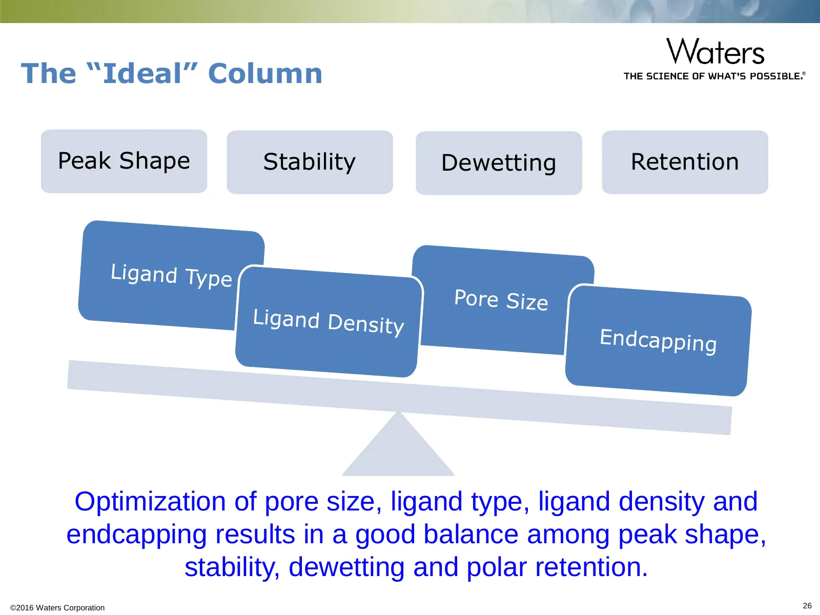
Slide 26: The "Ideal" Column
The “Ideal” Column Peak Shape Stability Dewetting Retention Optimization of pore size, ligand type, ligand density and endcapping results in a good balance among peak shape, stability, dewetting and polar retention. ©2016 Waters Corporation 26
Slide 27: Designing the Ideal Column
Designing the Ideal Column Q: How can reversed-phase columns designed for polar compound retention be improved? – Increase retention – Improve column lifetime at low pH – Provide better peak shape at neutral pH – Little-to-no MS bleed – Seamless scalability from UPLC-UHPLC-HPLC-Preparative separat
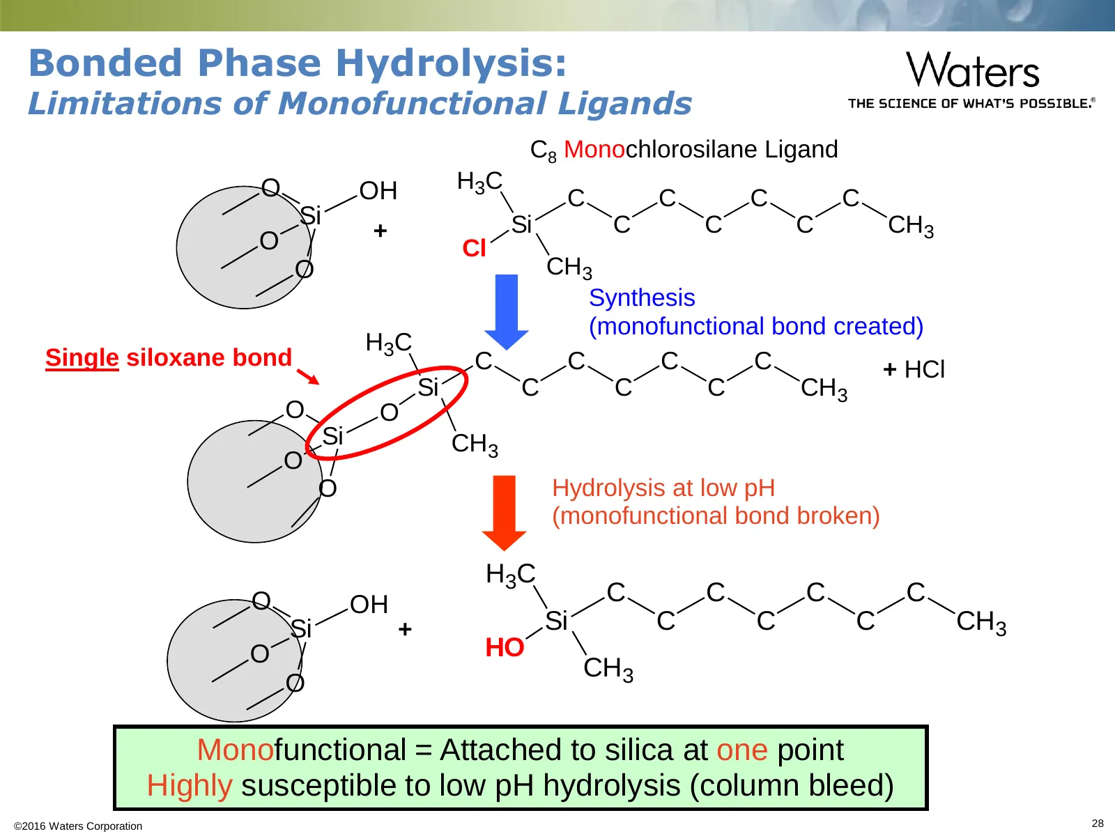
Slide 28: Bonded Phase Hydrolysis: Limitations of Monofunctional Ligands
Bonded Phase Hydrolysis: Limitations of Monofunctional Ligands C8 Monochlorosilane Ligand O OH H3C C C C C Si Si C C C CH3 O + Cl O CH3 Synthesis (monofunctional bond created) H3C Single siloxane bond C C C C + HCl Si C C C CH3 O O Si CH3 O O Hydrolysis at low pH (monofunctional bond broken) H3C O O
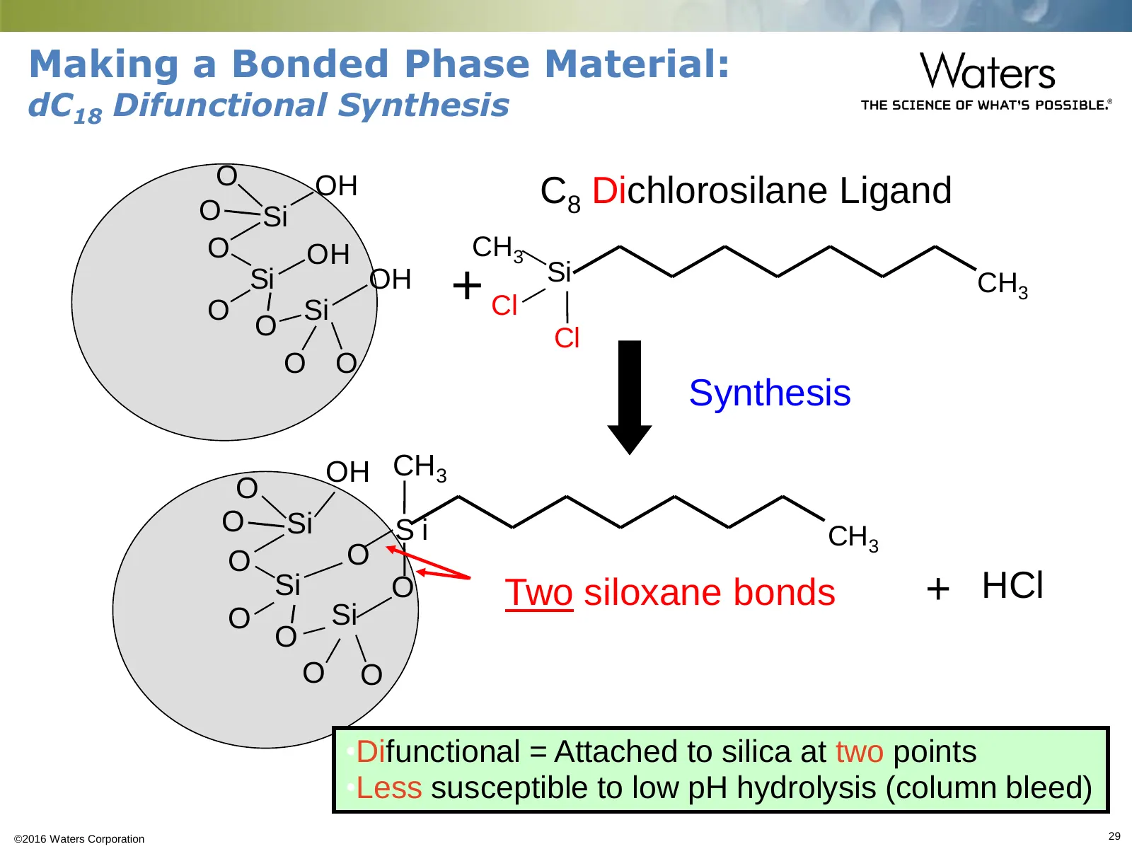
Slide 29: Making a Bonded Phase Material: dC18 Difunctional Synthesis
Making a Bonded Phase Material: dC18 Difunctional Synthesis O O Si OH •C8 Dichlorosilane Ligand O OH •CH3 O Si Si OH •+•Cl •Si •CH3 O •Cl O O •Synthesis OH •CH3 O O Si Si •CH3 O O Si Si O •Two siloxane bonds •+ •HCl O O O O •Difunctional = Attached to silica at two points •Less susceptible to low pH
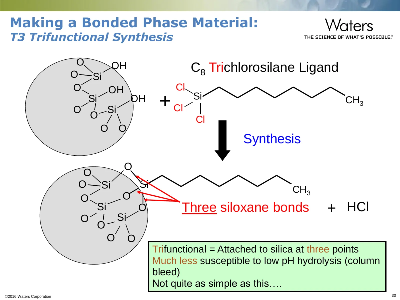
Slide 30: Making a Bonded Phase Material: T3 Trifunctional Synthesis
Making a Bonded Phase Material: T3 Trifunctional Synthesis O O Si OH •C8 Trichlorosilane Ligand O OH •Cl O Si Si OH •+•Cl •Si •CH3 O •Cl O O •Synthesis O O O Si Si •CH3 O O Si O •Three siloxane bonds •+ •HCl O Si O O O Trifunctional = Attached to silica at three points Much less susceptible to low p
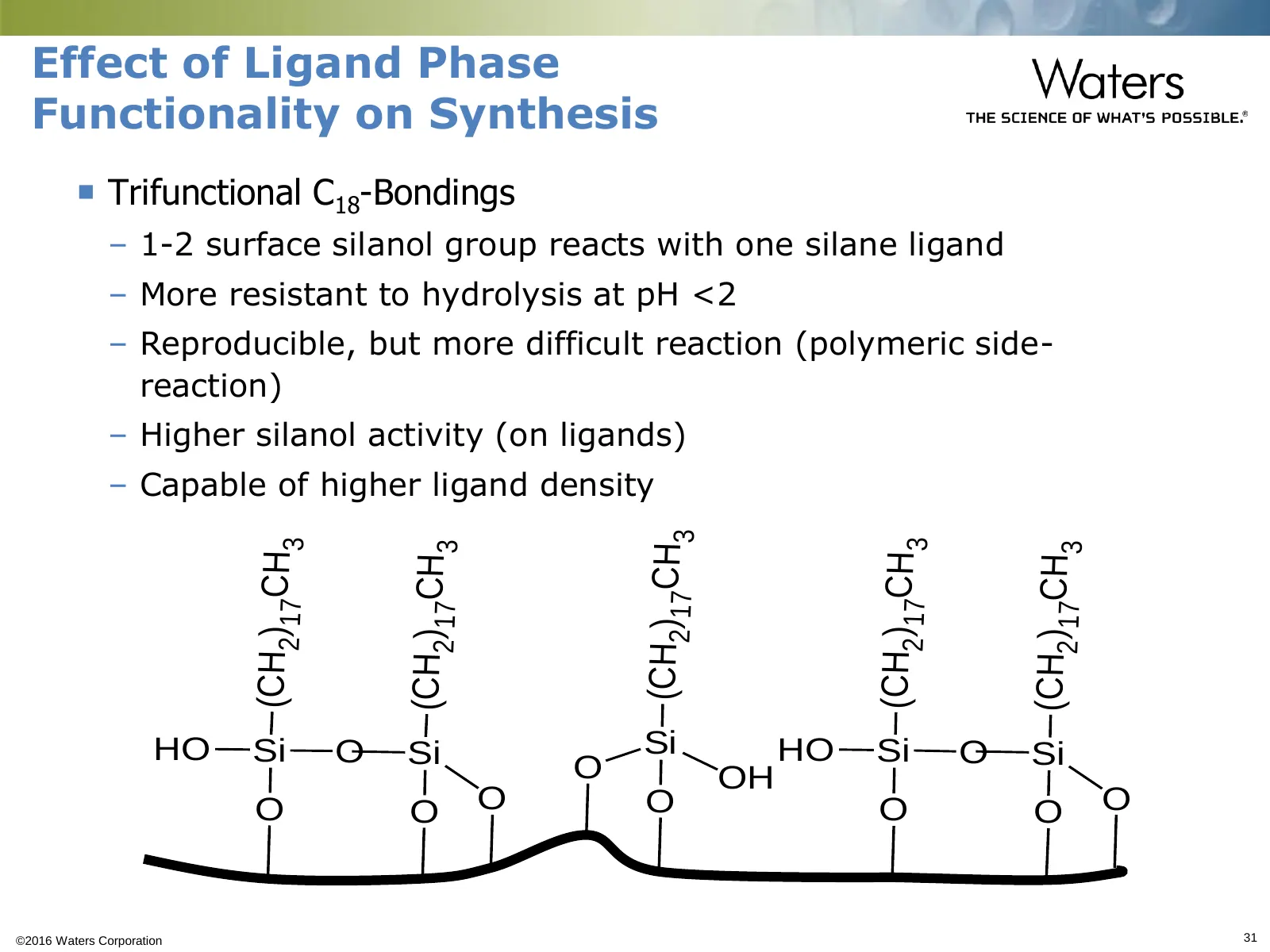
Slide 31: Effect of Ligand Phase Functionality on Synthesis
Effect of Ligand Phase Functionality on Synthesis Trifunctional C18-Bondings – 1-2 surface silanol group reacts with one silane ligand – More resistant to hydrolysis at pH <2 – Reproducible, but more difficult reaction (polymeric side- reaction) – Higher silanol activity (on ligands) – Capable of
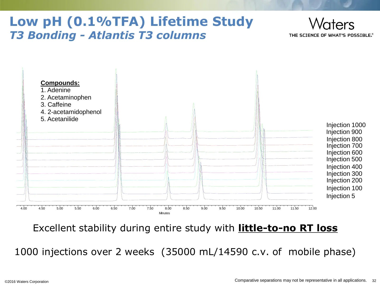
Slide 32: Low pH (0.1%TFA) Lifetime Study
Low pH (0.1%TFA) Lifetime Study T3 Bonding - Atlantis T3 columns Compounds: 1. Adenine 2. Acetaminophen 3. Caffeine 4. 2-acetamidophenol 5. Acetanilide Injection 1000 Injection 900 Injection 800 Injection 700 Injection 600 Injection 500 Injection 400 Injection 300 Injection 200 Injection 100 Injecti
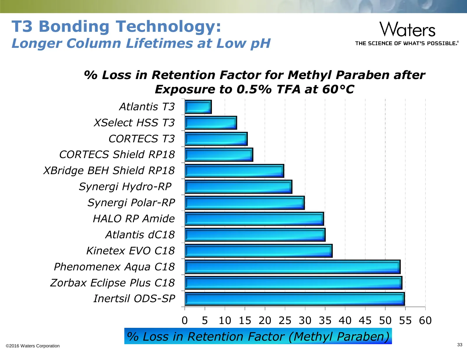
Slide 33: T3 Bonding Technology: Longer Column Lifetimes at Low pH
T3 Bonding Technology: Longer Column Lifetimes at Low pH % Loss in Retention Factor for Methyl Paraben after Exposure to 0.5% TFA at 60°C Atlantis T3 XSelect HSS T3 CORTECS T3 CORTECS Shield RP18 XBridge BEH Shield RP18 Synergi Hydro-RP Synergi Polar-RP HALO RP Amide Atlantis dC18 Kinetex EVO C18 Ph
Slide 34: How Do T3 Columns Work?
How Do T3 Columns Work? T3 columns are designed to maximize the dominant reversed- phase (van der Waals forces – hydrophobic attraction) retention mechanism – Retention maximized using 100% aqueous mobile phases – Retention maximized by using reduced C18 coverage o Polar analytes can “fit” between
Slide 35: How Does T3 Bonding Work for both Nonpolar and Polar molecules?
How Does T3 Bonding Work for both Nonpolar and Polar molecules? NonPolar – Retention mechanism is classic reversed-phase, hydrophobic interaction with the C18 stationary phase Polar – Dominant retention mechanism is still reversed-phase o Retention maximized using 100% aqueous mobile phases (ena
Slide 36: T3 Particle Technology
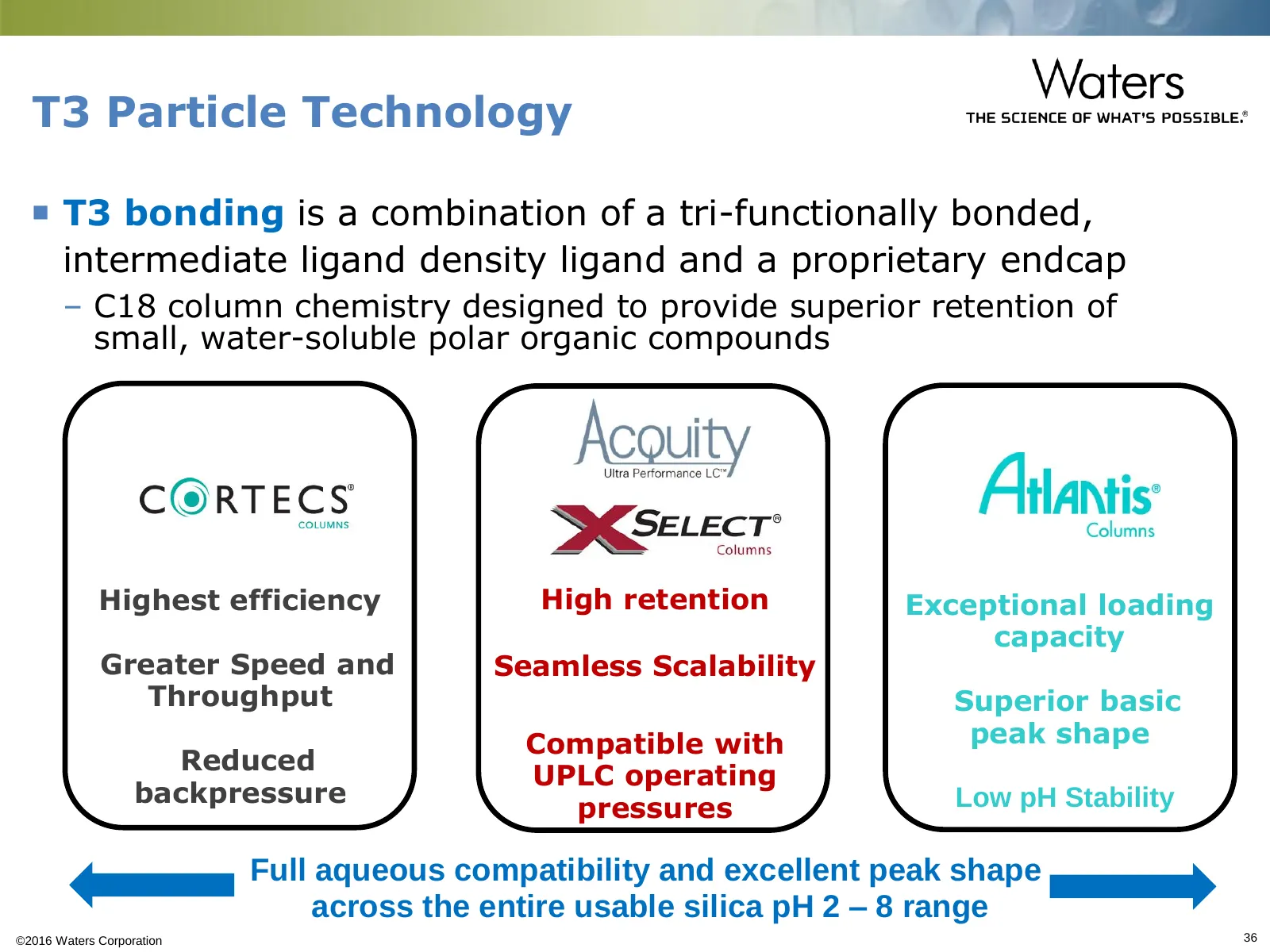
T3 Particle Technology T3 bonding is a combination of a tri-functionally bonded, intermediate ligand density ligand and a proprietary endcap – C18 column chemistry designed to provide superior retention of small, water-soluble polar organic compounds Highest efficiency High retention Exceptional l
Slide 37: Atlantis T3 Columns: Superior Polar Compound Retention
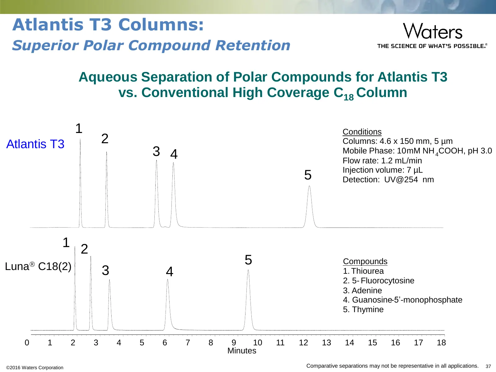
Atlantis T3 Columns: Superior Polar Compound Retention Aqueous Separation of Polar Compounds for Atlantis T3 vs. Conventional High Coverage C18 Column 1 Conditions Atlantis T3 2 Columns: 4.6 x 150 mm, 5 µm 3 4 Mobile Phase: 10 mM NH 4COOH, pH 3.0 Flow rate: 1.2 mL/min Injection volume: 7 µL 5 Detect
Slide 38: Atlantis T3 Columns: Superior Retention and Peak Shape
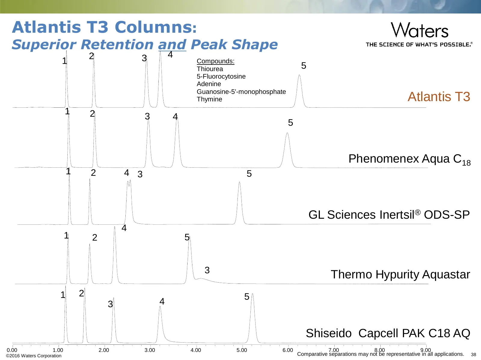
Atlantis T3 Columns: Superior Retention and Peak Shape •2 •3 •4 •1 • Compounds: •5 1. Thiourea 2. 5-Fluorocytosine 3. Adenine •Atlantis T3 4. Guanosine-5'-monophosphate 5. Thymine •1 •2 •3 •4 •5 •Phenomenex Aqua C18 •1 •2 •4 •3 •5 •GL Sciences Inertsil® ODS-SP •4 •1 •2 •5 •3 •Thermo Hypurity Aquasta
Slide 39: pH 7 Peak Shape & Selectivity Test
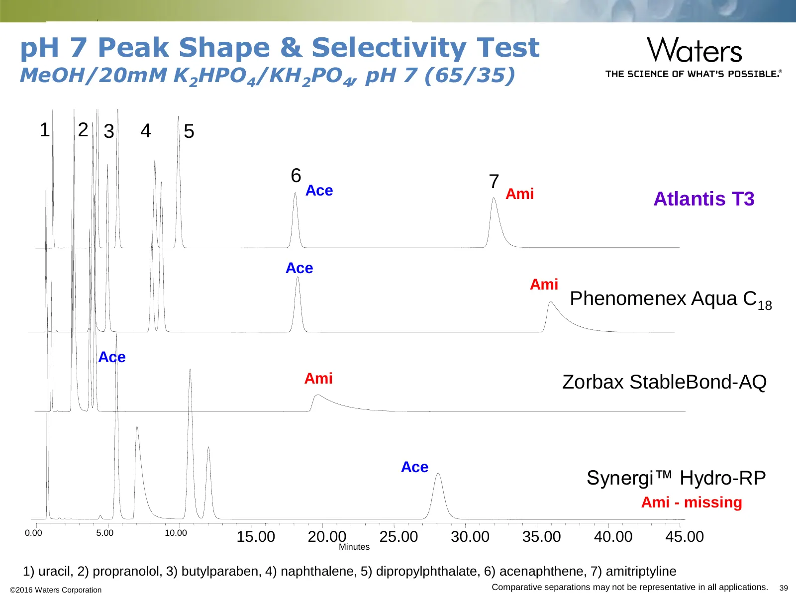
pH 7 Peak Shape & Selectivity Test MeOH/20mM K2HPO4/KH2PO4, pH 7 (65/35) 1 2 3 4 5 6 7 Ace Ami Atlantis T3 Ace Ami Phenomenex Aqua C18 Ace Ami •Zorbax StableBond-AQ Ace Synergi™ Hydro-RP Ami - missing 0.00 5.00 10.00 15.00 20.00 25.00 30.00 35.00 40.00 45.00 Minutes 1) uracil, 2) propranolol, 3) but
Slide 40: Superior Peak Shape and Retention: Superior Polar Compound Loading
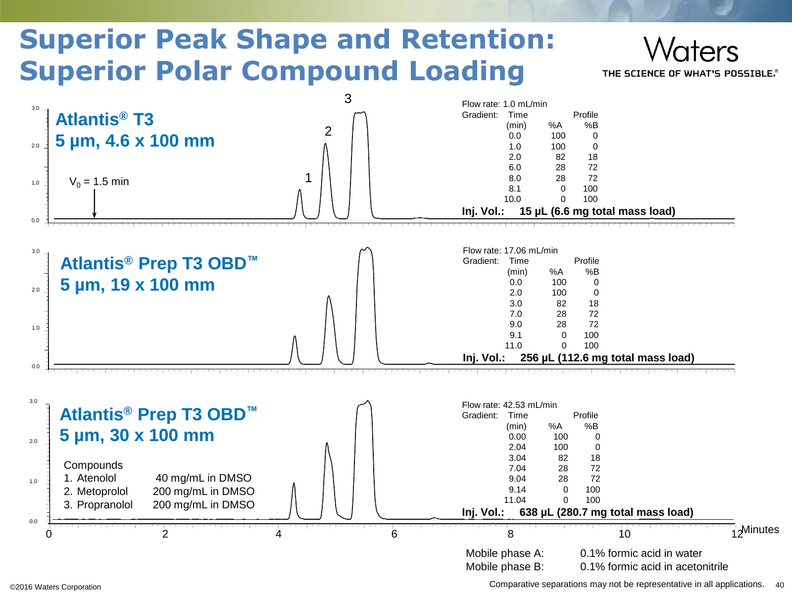
Superior Peak Shape and Retention: Superior Polar Compound Loading 3 Flow rate: 1.0 mL/min 3.0 Gradient: Time Profile Atlantis® T3 (min) %A %B 2 0.0 100 0 2.0 5 µm, 4.6 x 100 mm 1.0 100 0 2.0 82 18 6.0 28 72 1.0 V0 = 1.5 min 1 8.0 28 72 8.1 0 100 10.0 0 100 Inj. Vol.: 15 µL (6.6 mg total mass load)
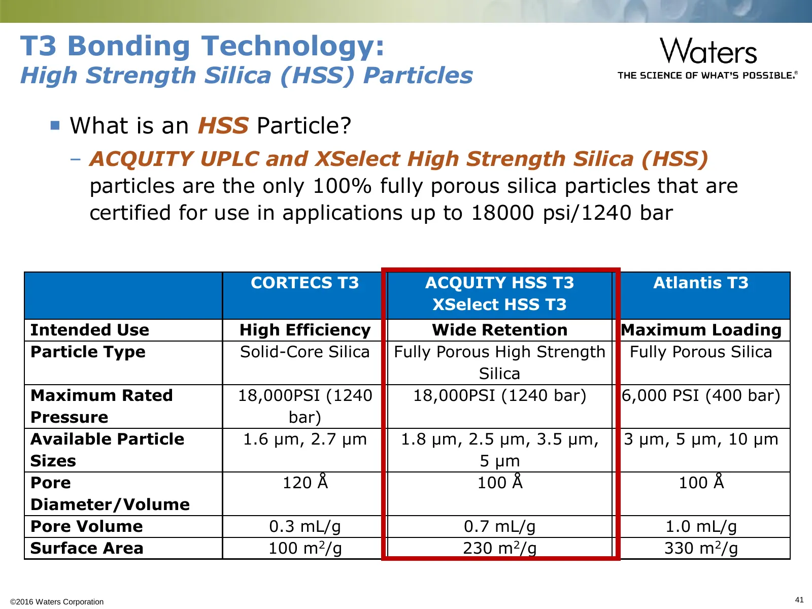
Slide 41: T3 Bonding Technology: High Strength Silica (HSS) Particles
T3 Bonding Technology: High Strength Silica (HSS) Particles What is an HSS Particle? – ACQUITY UPLC and XSelect High Strength Silica (HSS) particles are the only 100% fully porous silica particles that are certified for use in applications up to 18000 psi/1240 bar CORTECS T3 ACQUITY HSS T3 Atlanti
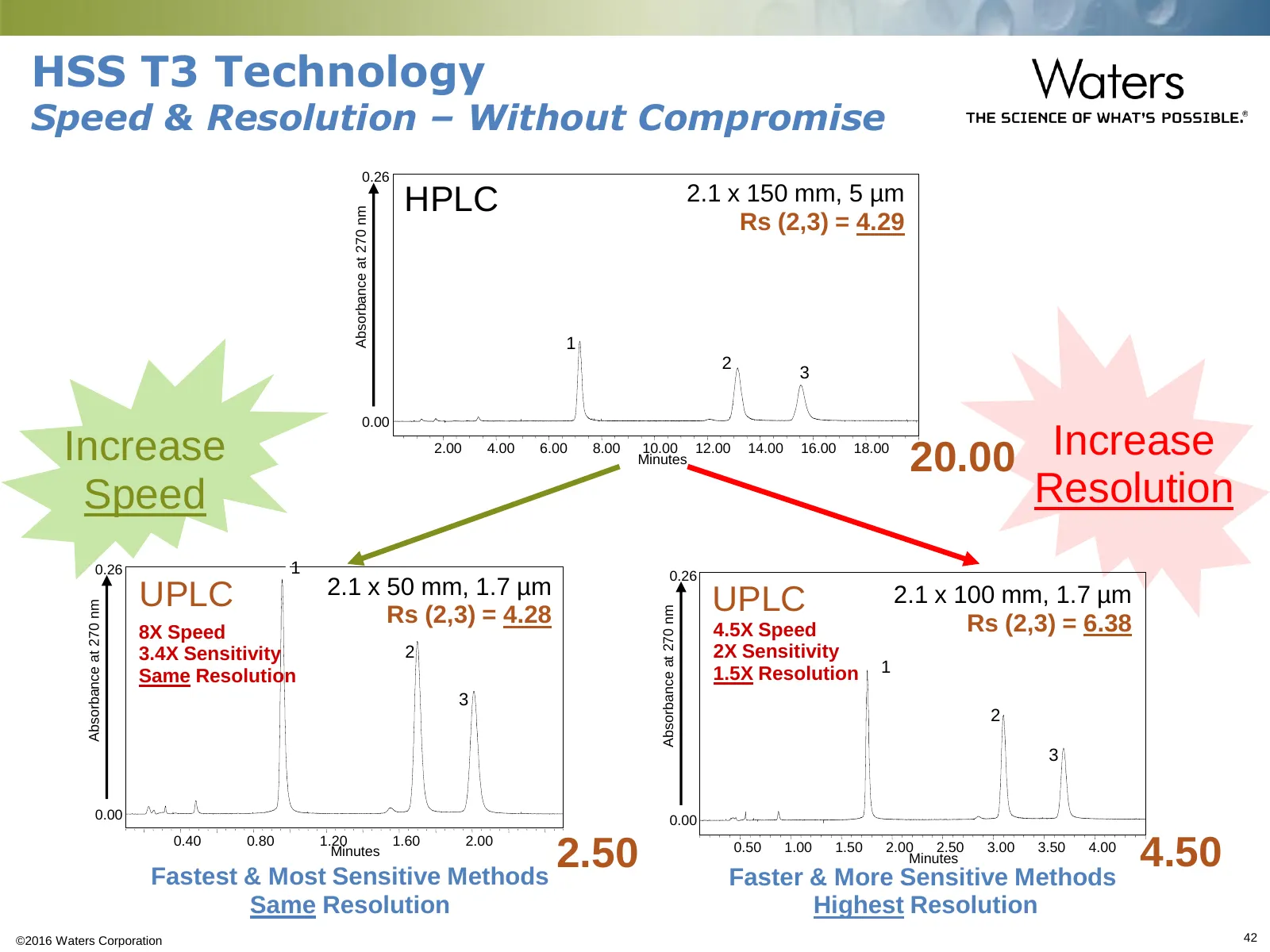
Slide 42: HSS T3 Technology: Speed & Resolution – Without Compromise
HSS T3 Technology Speed & Resolution – Without Compromise •0.26 HPLC •2.1 x 150 mm, 5 µm •Absorbance at 270 nm •Rs (2,3) = 4.29 •1 •2 •3 •0.00 Increase •2.00 •4.00 •6.00 •8.00 •10.00 •12.00 •14.00 •16.00 •18.00 •Minutes •20.00 Increase Speed Resolution •0.26 •1 •0.26 UPLC •2.1 x 50 mm, 1.7 µm •2.1 x
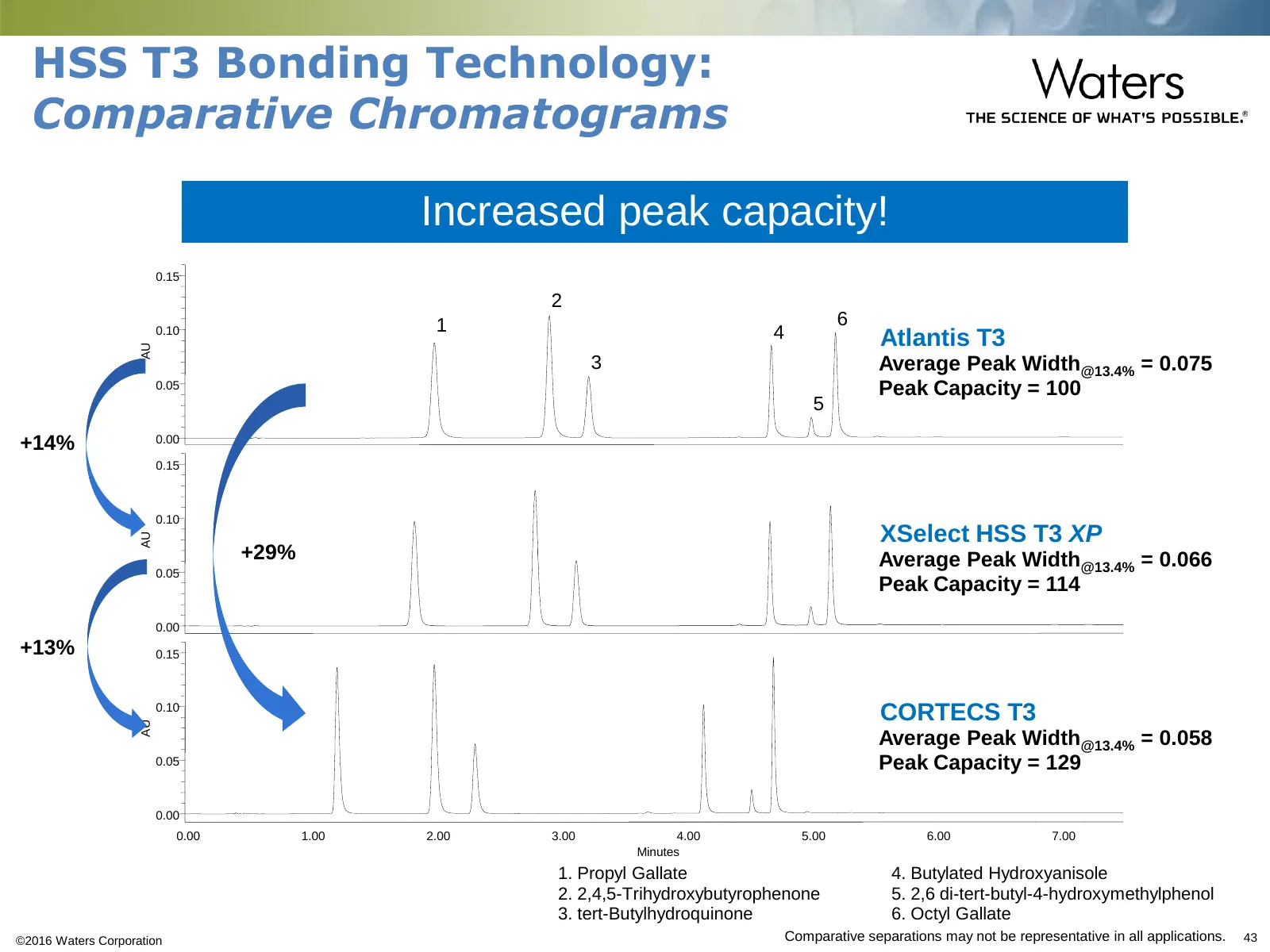
Slide 43: HSS T3 Bonding Technology: Comparative Chromatograms
HSS T3 Bonding Technology: Comparative Chromatograms Increased peak capacity! •0.15 •2 •1 •6 •0.10 •4 •Atlantis T3 •AU •3 •Average Peak Width@13.4% = 0.075 •0.05 •Peak Capacity = 100 •5 •+14% •0.00 •0.15 •0.10 •XSelect HSS T3 XP •AU •+29% •Average Peak Width@13.4% = 0.066 •0.05 •Peak Capacity = 114
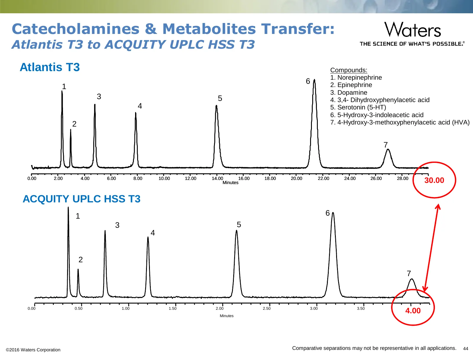
Slide 44: Catecholamines & Metabolites Transfer: Atlantis T3 to ACQUITY UPLC HSS T3
Catecholamines & Metabolites Transfer: Atlantis T3 to ACQUITY UPLC HSS T3 •Atlantis T3 Compounds: 1. Norepinephrine •6 •1 2. Epinephrine 3. Dopamine •3 •5 4. 3,4- Dihydroxyphenylacetic acid •4 5. Serotonin (5-HT) 6. 5-Hydroxy-3-indoleacetic acid •2 7. 4-Hydroxy-3-methoxyphenylacetic acid (HVA) •7 •0
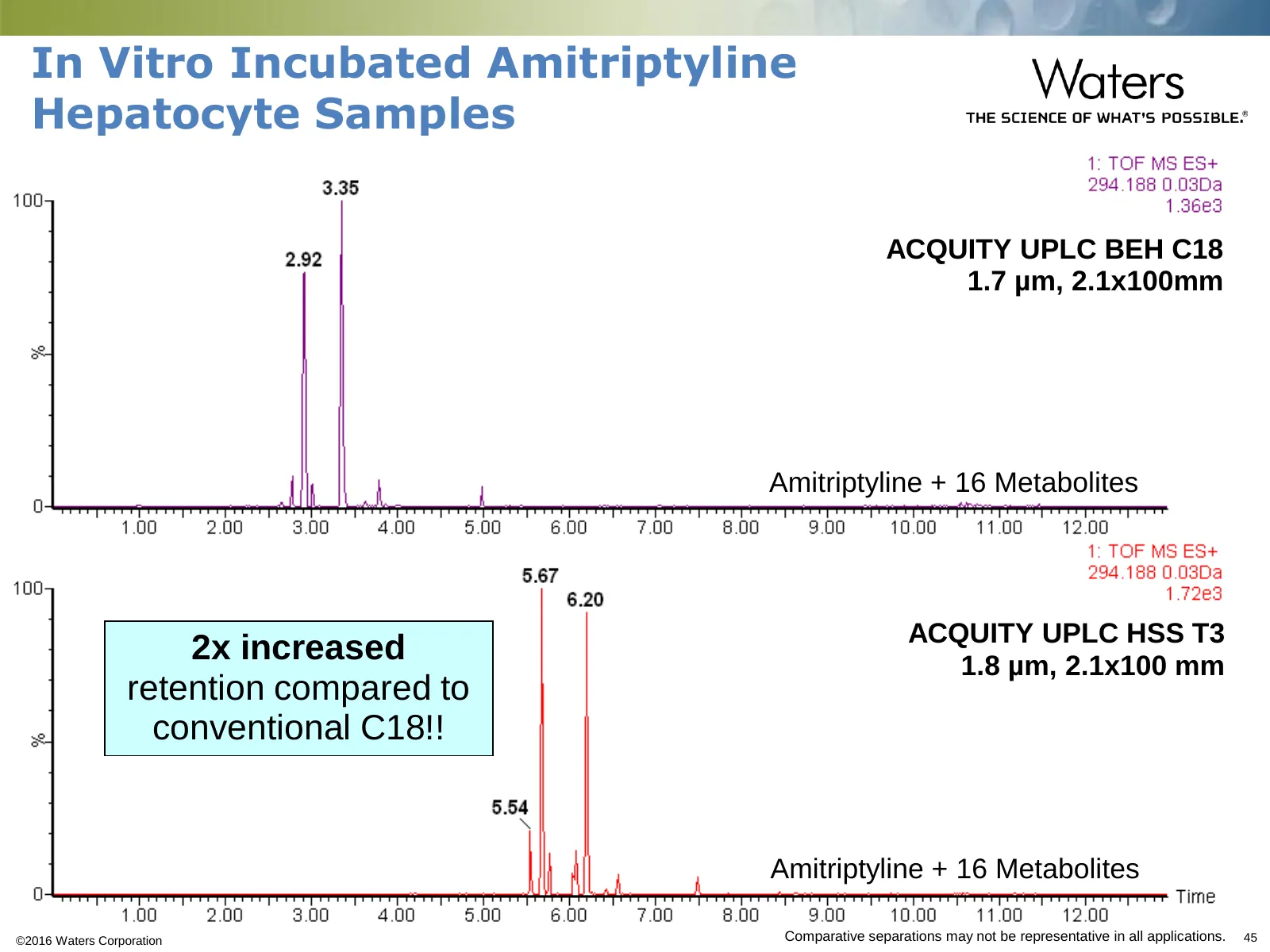
Slide 45: In Vitro Incubated Amitriptyline Hepatocyte Samples
In Vitro Incubated Amitriptyline Hepatocyte Samples ACQUITY UPLC BEH C18 1.7 µm, 2.1x100mm Amitriptyline + 16 Metabolites ACQUITY UPLC HSS T3 2x increased 1.8 µm, 2.1x100 mm retention compared to conventional C18!! Amitriptyline + 16 Metabolites ©2016 Waters Corporation •Comparative separations may
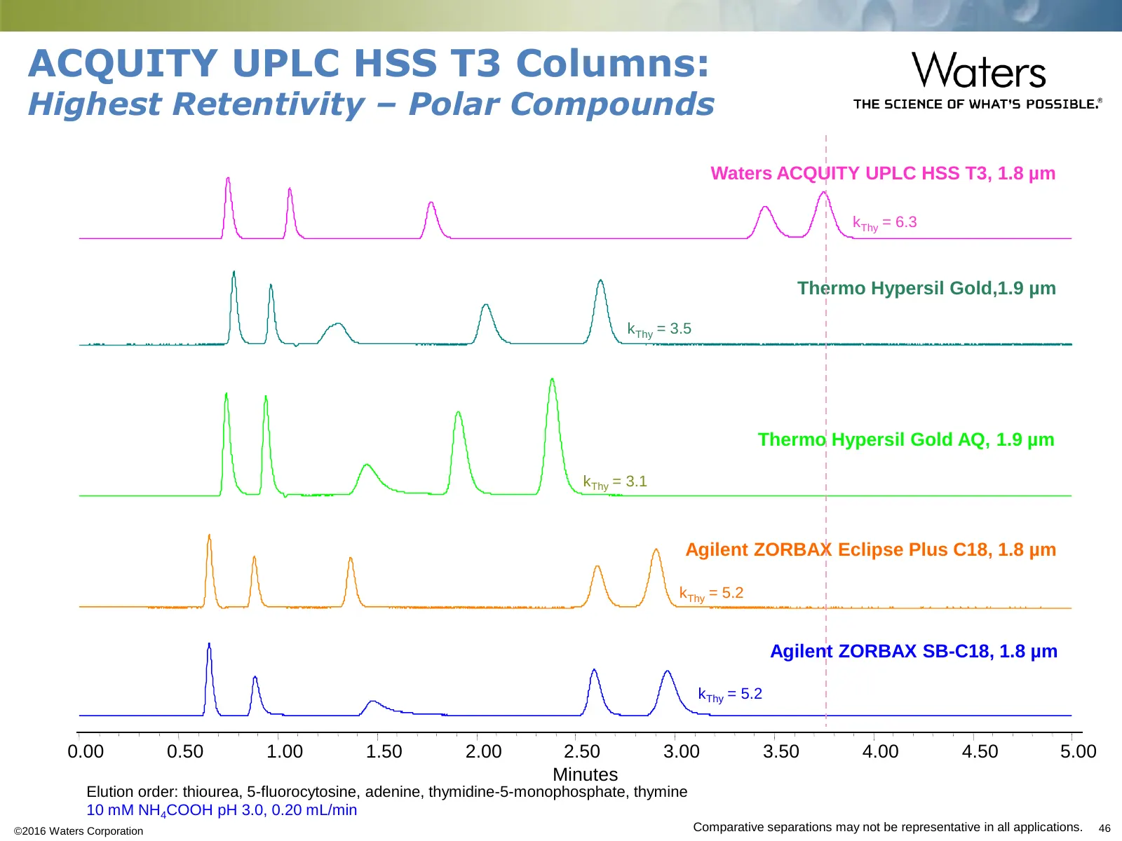
Slide 46: ACQUITY UPLC HSS T3 Columns: Highest Retentivity – Polar Compounds
ACQUITY UPLC HSS T3 Columns: Highest Retentivity – Polar Compounds •Waters ACQUITY UPLC HSS T3, 1.8 µm •kThy = 6.3 •Thermo Hypersil Gold,1.9 µm •kThy = 3.5 •Thermo Hypersil Gold AQ, 1.9 µm •kThy = 3.1 •Agilent ZORBAX Eclipse Plus C18, 1.8 µm •kThy = 5.2 •Agilent ZORBAX SB-C18, 1.8 µm •kThy = 5.2 •0.
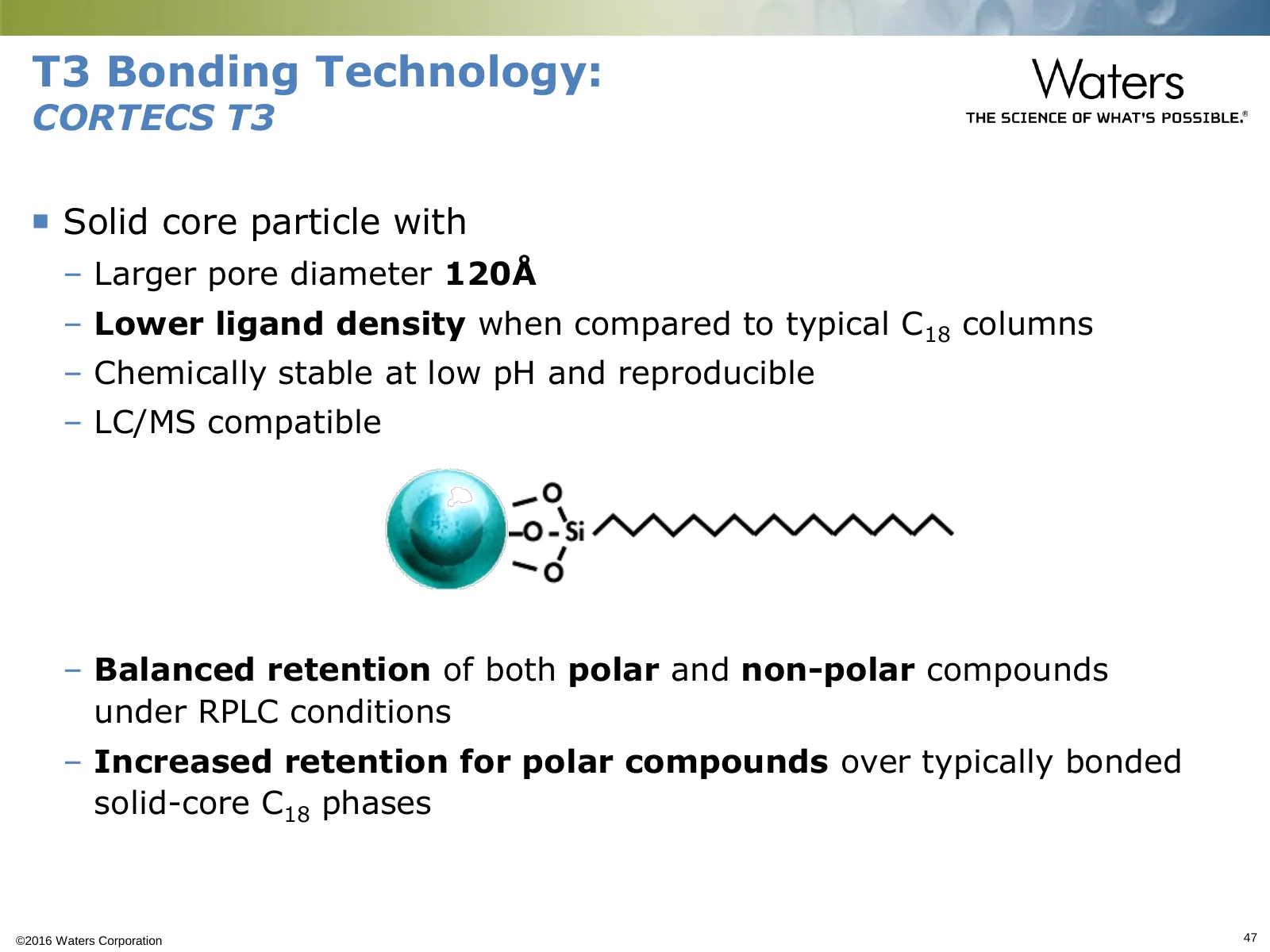
Slide 47: T3 Bonding Technology: CORTECS T3
T3 Bonding Technology: CORTECS T3 Solid core particle with – Larger pore diameter 120Å – Lower ligand density when compared to typical C18 columns – Chemically stable at low pH and reproducible – LC/MS compatible – Balanced retention of both polar and non-polar compounds under RPLC conditions – In
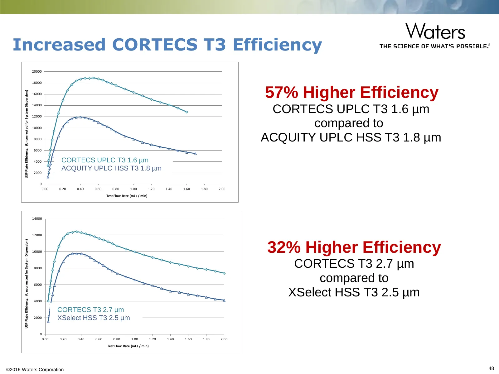
Slide 48: Increased CORTECS T3 Efficiency
Increased CORTECS T3 Efficiency 20000 18000 •57% Higher Efficiency USP Plate Efficiency, (Uncorrected for System Dispersion) 16000 •CORTECS UPLC T3 1.6 µm 14000 12000 10000 compared to 8000 •ACQUITY UPLC HSS T3 1.8 µm 6000 4000 •CORTECS UPLC T3 1.6 µm •ACQUITY UPLC HSS T3 1.8 µm 2000 0 0.00 0.20 0.4
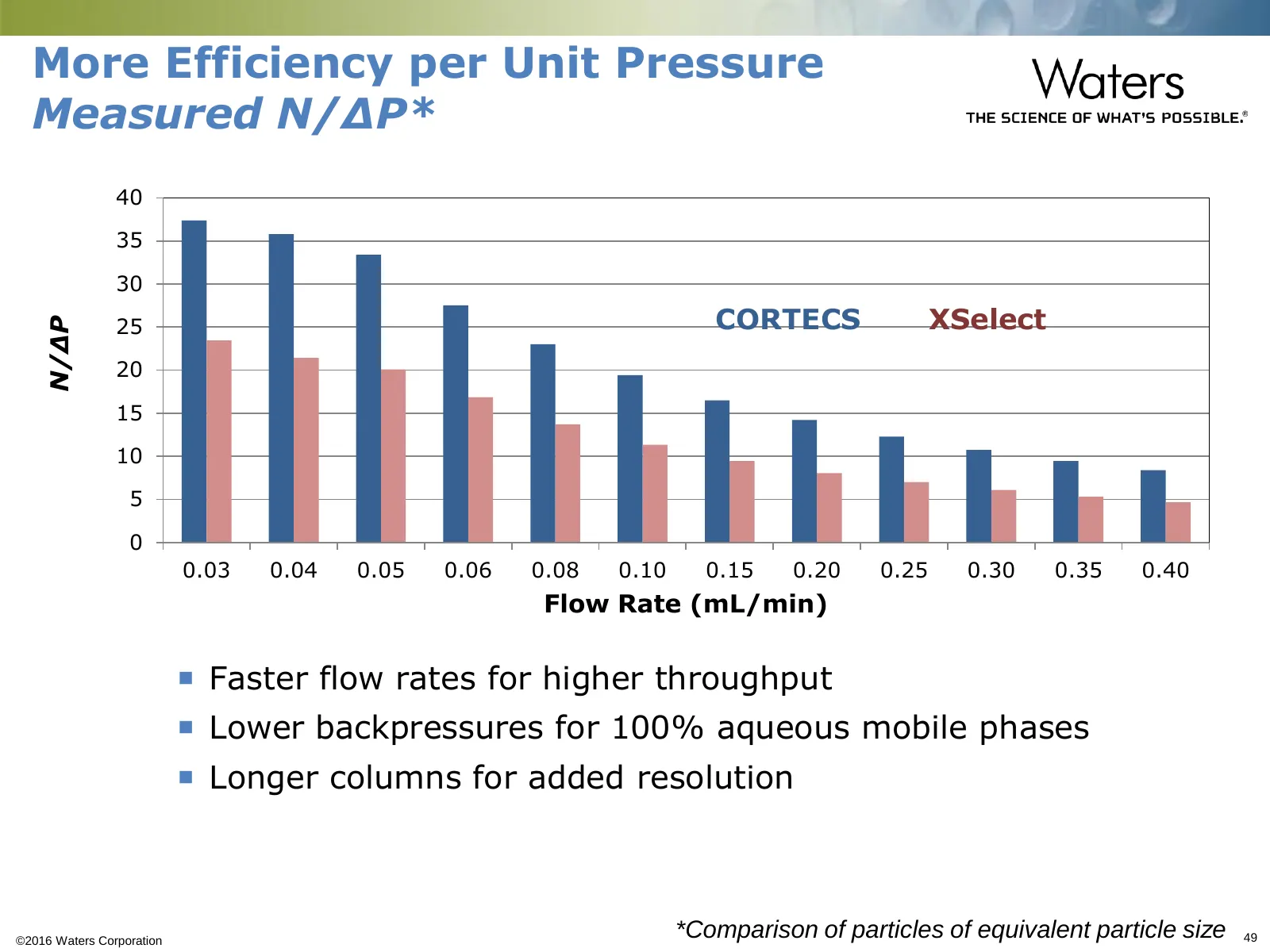
Slide 49: More Efficiency per Unit Pressure
More Efficiency per Unit Pressure Measured N/ΔP* 40 35 30 25 CORTECS XSelect N/ΔP 20 15 10 5 0 0.03 0.04 0.05 0.06 0.08 0.10 0.15 0.20 0.25 0.30 0.35 0.40 Flow Rate (mL/min) Faster flow rates for higher throughput Lower backpressures for 100% aqueous mobile phases Longer columns for added reso
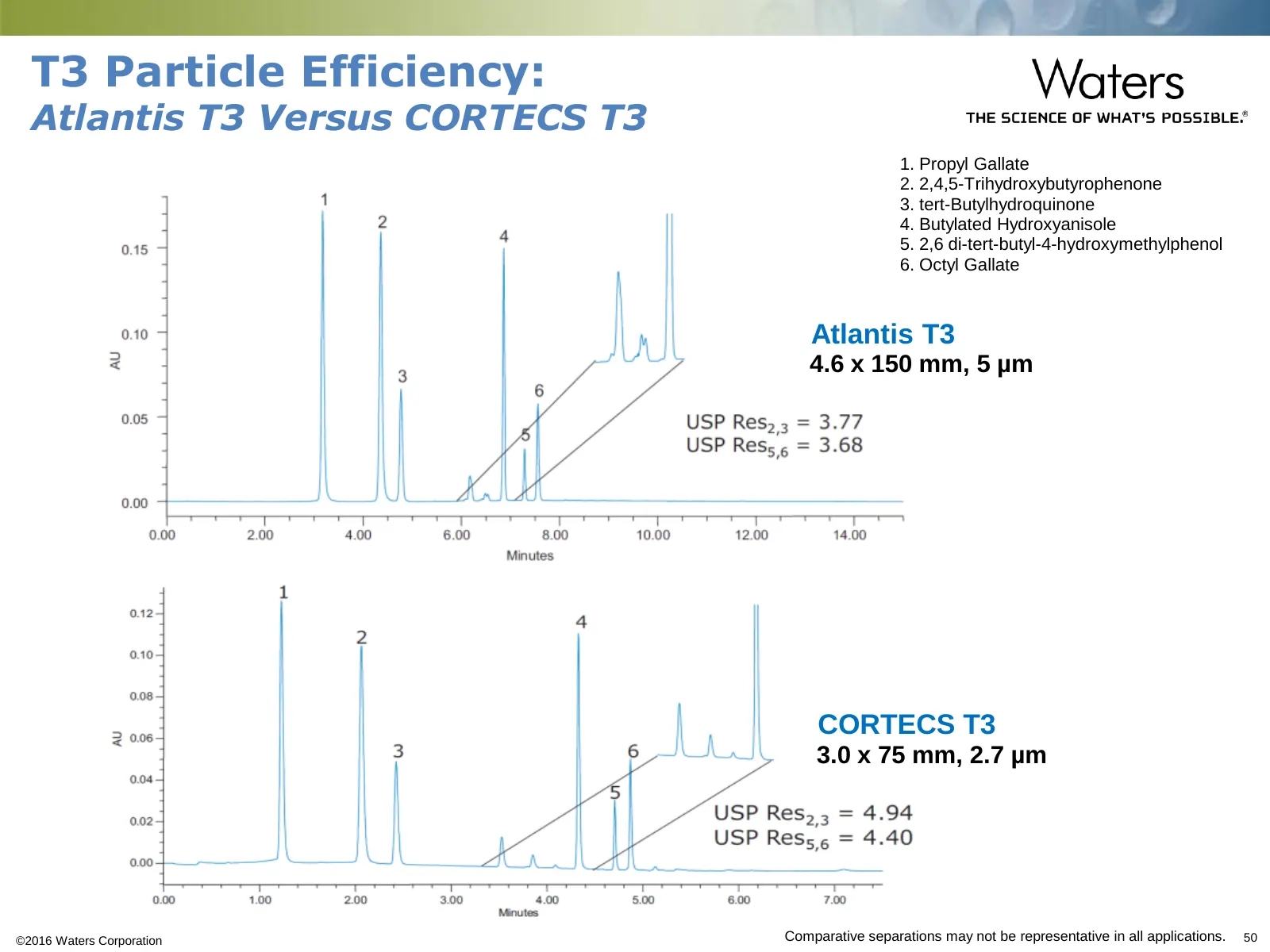
Slide 50: T3 Particle Efficiency: Atlantis T3 Versus CORTECS T3
T3 Particle Efficiency: Atlantis T3 Versus CORTECS T3 1. 1. Propyl Gallate 2. 2. 2,4,5-Trihydroxybutyrophenone 3. 3. tert-Butylhydroquinone 4. 4. Butylated Hydroxyanisole 5. 5. 2,6 di-tert-butyl-4-hydroxymethylphenol 6. 6. Octyl Gallate •Atlantis T3 •4.6 x 150 mm, 5 µm •CORTECS T3 •3.0 x 75 mm, 2.7
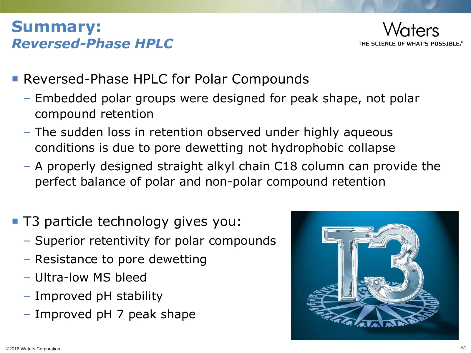
Slide 51: Summary: Reversed-Phase HPLC
Summary: Reversed-Phase HPLC Reversed-Phase HPLC for Polar Compounds – Embedded polar groups were designed for peak shape, not polar compound retention – The sudden loss in retention observed under highly aqueous conditions is due to pore dewetting not hydrophobic collapse – A properly designed st

Slide 52: Thank You! Live Q&A Session
Thank You! Live Q&A Session ©2016 Waters Corporation 52
Source: Internet Archive copy of waters.com
More decks from Waters Corporation
 Q3 2026 Earnings Presentation30 slides · Nov 3, 2026
 Q2 2026 Earnings Presentation33 slides · Aug 4, 2026
 Q1 2026 Earnings Presentation29 slides · May 5, 2026
 Q4 2025 Earnings Presentation22 slides · Feb 9, 2026
 J.P. Morgan 44th Annual Healthcare Conference (January 2026)29 slides · Jan 12, 2026
 J.P. Morgan 43rd Annual Healthcare Conference (November 2025)38 slides · Nov 11, 2025